

The ZN414 is designed solely for AM but NBFM signals can be copied adequately by off-tuning the receiver a little (slope detection). The ZN414 could also be replaced with the more recent ZN416 IC to provide 18dB more gain. I have left the pin numbers to you as they are readily available in the Maplins (and other) catalogues. The 2 IF transformers are 465KHz coils robbed from another one of those cheap'n-nasty $1.5 radio's.
The 741 OP-AMP will drive a 70 ohm headphone quite easily. 70 ohm headphones are cheap and available as replacements for the "Sony Walkman", but with both headphones wired in seried (only use TIP and RING of the 3.5mm connector). In my lab-book, I made a note to place a 560 ohm resistor between the 741 output and the +ve supply. This is to force one of the O/P transistors to draw some current in order to prevent crossover distortion. OP-AMPS make good low power AF amplifiers but they do have their limitations.
The circuit shown above describes the antenna input circuit for 145MHz but you can change it for whatever band you want from 70 KHz to over 200 MHz, with a suitable local oscillator of course.
The local oscillator can be an HF/VHF Signal Generator but if you want a self contained unit, then a custom local oscillator should be constructed. I have also given the three oscillator circuits I have used for various applications in the following GIF files:

Gives the circuit diagram of a VHF 145MHz oscillator that can be used to receive the 2 meter band. The crystal is a 2-meter 8MHz type (Kenwood 2200) but 12MHz crystals will work equally well in this circuit. If you want to receive 145.750 use a TX crystal from 145.250 - 145.300 (RTTY channel). Tweek the two IF cans (change the IF) to peak the channel required.

Is a crystal controlled RX for 27 MHz. Crystals are readily available. Here is the frequency of R/C band crystals.
26.995, 26.540 - Brown
27.045, 26.590 - Red
27.095, 26.640 - Orange
27.145, 26.690 - Yellow
27.195, 26.740 - Green
27.245, 27.790 - Blue
Almost any crystal can be made to "hoot" at its fundamental frequency, 3rd harmonic or 5th harmonic, just by changing the tuning coil and capacitor. A GDO is a great help here.
USA CB TX crystals will get you into the 28 MHz amateur band.
A 16.5 MHz crystal will get you into the 50 MHz amateur band.
A 14.0 MHz crystal will get you into the 70 MHz amateur band.
Get the RX aligned to the exact frequency by adjusting the IF transformers. Changing the IF frequency will change the RX RF frequency by about plus/minus 40 KHz.

Is a VFO which can cover any frequency you like from 70KHz to over 20MHz, but stability may suffer at high frequencies. L1 and C1 you should select for the band you want. The 47pf and 100pf capacitors should always have the same ratio. Their SUM being about C1/2.
If you are particularly adept at construction and can produce a stable VFO at VHF then there is no reason why you cannot make a tuneable VHF receiver with this circuit.
I hope that you have as much fun with this receiver as I had over the years. One of the next projects I will soon post soon will be the TX used with this receiver. I was fortunate enough to live on a hill where the path losses from me to GB3PI was only 109dB. This meant that I could open the squelch of GB3PI with only 20uW (MICRO not MILLI)!! I modified the IF coils of this receiver (took out the internal capacitors and used external caps) so that the IF was 600KHz. The transmitter was also the local oscillator for the receiver!!! The transmitter gave out over 1mW. Antenna switching was the only TX/RX switching used, ie the TX was always left switched on. One thing about QRP - you never have to worry about SWR!!
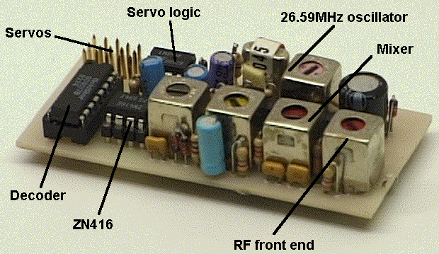
As usual all circuits and ideas are presented as ideas that were succesful for me, with the components I had handy at the time. You may have to "fiddle" with coil turns and capacitances, etc., depending upon the coil formers and layout you choose to use. Here is a picture of one of my prototypes which I used as a five channel proportional receiver for radio control.

This shows how I re-use IF transformers from the cheap'n nasty radio sets. In this circuit I used a ZN416 which is a ZN414 but with an additional 20dB AF amplifier. The decoder logic OP-Amps and servo driver IC are only required for radio control. I ran out of space on the PCB otherwise I could have had outputs for up to nine proportional channels.
Have fun, de HARRY, Lunda, Sweden.