swlradioph1k.gif
 Short
wave lradio
Short
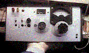
wave lradioI will show you one of my first projects. I made it about 13 years ago. This is a radio. It does not have RF amplifier. It has two stage of IF amplifier. It is a normal single super radio. It has beat frequency oscillator and S meter. See the circuit! Oscillator makes from 4MHz to 12MHz. It can receive From 3.55MHz to 11.55 MHz. Originally I planed to inject the oscillated signal on the gate of the mixer. But the connection capacitor has no need. The same thing was happen on the grid injection of the tube receiver. The frequency of the mixer and oscillator is changed by the double variable capacitor. It does not have some tracking system. The core of the mixer's coil is tuned to get a good gain on the 7MHz. Therefore the gain of 10MHz and 4MHz is not so good. The tuner variable capacitor is made by that of AM radio. The sub tuner capacitor is connected parallel for that. And 1/20 gear is used for the spread capacitor. One turn of it makes 10KHz of the frequency. Therefore I could tune on the ssb signal of 7MHz easy. Oscillator is a normal electric coupled oscillator (ECO). The oscillator is not have some special stabilizer. Therefore the frequency is not so static. From the timing of the power on, it need about ten minutes to be used for ssb signal receiving. I made no power switch on this machine, because I stayed the power everytime on. Some QRH happend by the change of the temperature. I could not open the window of my heated room on winter.This radio has two stage IF amplifier. It is constructed by source based amplifier. 2SK19 was popular name of this time. If this amplifier oscillates, you can omit the bypass capacitor on the source. It may be good to change the resister of the source. I used the ceramics filter for the AM radio. It is good in order to hear the short wave radio station. But it is too wide in order to hear the ssb signal. I have heard the strongest signal on the 7MHz ssb band. Detector is a normal diode AM detector. It is used for a product detector , when the BFO signal is injected in the drain of the diode. This circuit is used on the valve receiver. This detector has a high impedance output. Therefore I must use the FET buffer on the next stage.Audio amplifier is made by a transformer input single ended push pull circuit (TRANS-SEPP). I got this transformer from the broken radio. You can use LM386 or the head phone amplifier of my homepage. Output power of this amplifier is 500mW. It was enough for me. This project has an basic theme that simple and static . I wanted to make with no accessary. But the box is got from my failure projects. The failure projects has many accessary. You can see the many holes on the front panel. It was the hole of many switches of the last time. The S meter is already attached on the front panel. I could not permit to remain the big circle hole on the front panel. Therefore I attached the S meter. S meter is driven by the FET amplifier. But it is not so sensitive. Only the Moscow radio can drive this meter. I connected ten meter wire antenna and earth for this machine. I heard many radio station on the 7MHz and 9MHz. Voice of America, Radio Australia and Radio India was heard. I collected many BCL cards. I have heard many amateur station of 7MHz ssb. I got SWL-JCC 300 ( Award of 300 another cities in Japan). I have made activity of the radio amateur on the 21MHz CW with this machine with a simple crystal convertor. I got WAC ( Worked all continental) with this machine. I feels now that this machine has no originality. But I want to show you the first step to be the radio amateur. Do not try to make the ssb transceiver or FM handy on your first project.
<<箕荷: ATT00002.htm>
Dear Tinus I am very happy to receive such a letter. I will up link your letter on my home page No.91.
From: tinus[SMTP:prinst@intekom.co.za] Sent: Tuesday, May 23, 2000 19:07 To: jf10zl@intio.or.jp Subject: Fan and improvement Hi Kazuhiro, I am now a great fan of your circuits. I have build some of them and found that they practically work first time. I have made a set with a 2 standard oscilators and a pre-amp and an audio amp using LM386. This fits into a unit which have 8 X 5 blocks, my parts are then made into little blocks which can then just be places into this. With this concept I can build any design within minutes. Connecting is made up with the pins of IC sockets. I have build project 91 SWLRADIO.GIF and found it pretty smart. With playing around a bit I found that if I changed the IF1 coil arounf it improved the signal. Further I found that 2 coils back to back before the detector stage improved it even more. I you like I can redraw your circuit with my modifications. I use this radio with only short 300mm antenna and pick up amateurs and Radio Cape to boats from Johannesburg in South Africa. I have also replaced the OZL9 coil with OZL28 pairs and so on and it still works fine on other frequencies. I could perhaps also send gif file of my little invention for designing circuits quick without soldering. I have now turned most of the OZL coils for experimenting and find they work just fine. Next I will go over to one of your more complex circuit. Nice making contact with you. Tinus Prins South Africa
swlradioph2.gif
 短波受信機
短波受信機現存する機械の中で最も初期の作品をおみせします。高周波増幅無し。中間周波2段増幅のシングルスーパーで、ビート発振器付き。Sメーター付きです。回路図をご覧ください。発振器は4MHzから12MHzを発振します。受信範囲はこれより455kHz下の、3.55MHzから11.55MHzです。本来は、ミキサーにゲート注入するつもりだったのですが、結合コンデンサーを調節した所、無いのがベストでした。空中結合です。同様の事は、古い真空管の5極管ミキサーでも起こります。混合器(MIX)と発振器(OSC)は、2連バリコンで周波数を同時に変えられます。回路をご覧になってわかる様に、特別トラッキング調節がなく、7MHzで最大感度に発振器のコアを調節しているだけです。このため、10MHz以上や4MHz以下は一応受信できる物の感度がおちます。また、細かな同調を楽に取るため電気的スプレッドを採用し、さらにこのスプレッドバリコンは1/20の機械式減速機でダイアルからまわされます。結果的に、ダイアル1回転10KHzになっており、SSBの同調も楽々です。発振器は、簡単なECO発振器です。発振周波数は特別に安定化していません 。このため、電源ONから10分間程度は、SSBが受信出来ないほど、周波数変動があります。このため24時間電源は入れっぱなしでつかいます。温度変化にも弱く、冬場暖房した室内で使っている時は、窓を開けて空気の入れ替えが出来ません。中間周波増幅は2段です。ここは、何の変哲も無いゲート接地増幅器です。ここで使った2SK19よりも2SK241等のほうが良い性能がえられそうです。この機械をつくった、1985年当時、すでに、2SK19は古めの品番だったとおもいます。発振する場合には、ソースのバイパスコンデンサーを取ってしまうのが手です。あるいは、ソースの抵抗を10キロオーム等の大きな値にして、ドレイン電流をさげて、増幅率を下げるのも手です。ここでは200オームと470オームに落ち着いています。フィルターには、AMラジオ用の帯域幅10KHzのセラミックフィルターが使われています。本来短波放送受信用なので、これでOKでした。7MHzのSSBを受信する場合には、混信するので、出来るだけ強力な局を選んで受信するようにしていました。検波は、ゲルマニュームダイオードです。ここのドレインにBFOを注入して、簡易プロダ クト検波としています。今ならダイオードDBMとする所ですが、これも真空管時代の回路のなごりをとどめています。このタイプの検波器は、入出力インピーダンスが高くないとうまく動作しないので、低周波段の初段には、FETの緩衝増幅器を入れてあります。低周波増幅は、これも時代をあらわしていますが、トランス入力のSEPPです。ラジオを壊したときに、出てきた回路をそのままトランスとともに使っています。出力は500mWそこそこですが、十分です。実は、このラジオの製作の基本方針は「シンプルな回路で確実な動作、アクセサリーは少な目に」という物でした。箱の写真を見て頂くとわかるのですが、箱にはいらない穴があいています。この5年前ほどに、1度短波ラジオの製作に失敗した作品の、箱の再利用です。このため、Sメーターが、前の製作の時に付けられていました。基本方針に従うとここも無くして、大穴にする所でしたが、さすがに穴のおおきさにあきれてしまい、Sメーターが不本意ながら、付けてあります。このメーターは感度があまり良くなく、振り切れるのは「モスクワ放送」と「ペキン放送」くらいな物です。BFOを作動させるとBFO信号だけで振 り切れてしまうので、BFO作動時には、バイアスを与えています。このラジオに10メーターのワイアーアンテナと洗濯機用のアースをつないで、短波放送の受信や7MHzのSWLをやっていました。私はSWLのコールサインJA1−38215として、この受信機で、SWL−JCC300を取得しました。また、自作のクリコンと組み合わせて、21MHzCWで開局して、このラジオでWACも取得しました。いまから見れば、特徴の無い回路構成で、送信機と別に周波数調節しなければならない、不便な機械ですが、私にとっては、大事な機械です。皆さんも、自作を始めるなら、いきなりトランシバーやリニアーアンプではなく、こういった基本構成の受信機から始めるのが、失敗しない筋道です。そういった意味でご紹介する物です。
swlradio.gif

back to index