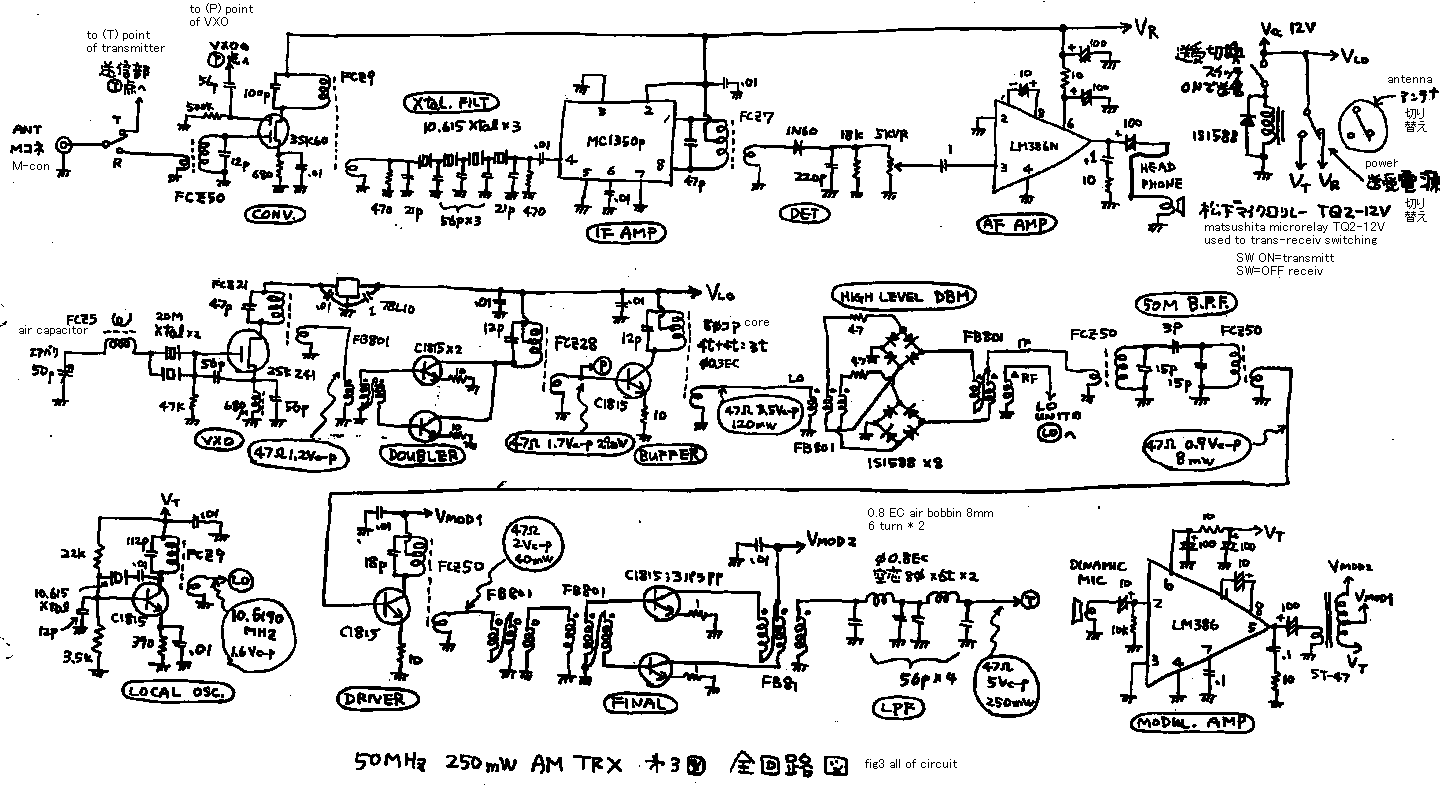
In Japan, we cannot hear the AM modulated signal except 50MHz in these days. And some of the operator of 50MHz AM use hand made rigs. I may introduce you about my simple and useful transceiver in this page. See fig 1! Receiver is constructed by a normal single super heterodyne. IF-frequency of it is 10.6MHz. Crystal filter is also home brew. See fig 3! Converter is made by double-gate-FET. 1st gate of it is 50MHz signal input. 2nd gate of it is 40MHz oscillator input. On the drain of this FET, there comes 10MHz IF signal as the different of these signals. Crystal filter is 4 element ladder. See fig 4! It is the character of the filter. It has some ripple on the pass-band. It is not so good but enough to use. See fig 3! IF AMP is made by MC1350p IC. It makes 54dB gain. Detector is made by germanium diode. And AF AMP is made by LM386 IC.
Oscillator is made by 20MHz VXO and doubler and buffer AMP. It is quite Normal .
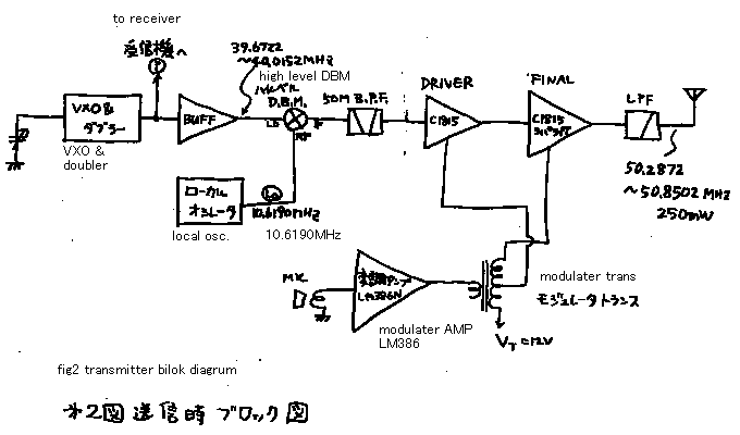
I will explain about transmitter. See fig 2! Oscillator signal (=39.6722 to 40.0152MHz) and local oscillator signal (=10.619MHz) is mixed on the high level DBM mixer. And it makes 50.28 to 50.85MHz signal. And the 50MHz signal is amplified by the two stage RF amplifier . Modulator is also made by LM386 IC. Modulator transformer is ST-47. This transformer is made to use push-pull-AF-AMP by the SANSUI company. This type of system is called as the high level modulator. 100% modulation is achieved. About the frequency planning of this 50MHz AM system, I got the hint from the introduction by Mr.Kanno(JR8DAG). If you have the back number of Japanese CQ magazine, please see it on the 1990 Feb. *** Please see table 1! I could make 11 QSO on one night on my local hill. Most DX of it was 120km. Lets make AM transceiver! And use it!!
50MHz 250mW トランシーバー
中学の頃、ゲルマラジオで7MHzのAMの信号を聞いた事があります。ほんとの話です。しかし、ほとんどのバンドで、帯域の広いAM変調は自然消滅し、近頃でもAMモードを使うことができるのは50MHzだけです。(どうもインドでは今でも7MHzAMが運用されているらしい。)そして,50MHzでAMを運用するアマチュアの内には,自作のリグを使っている方も大勢います。AM送信機は、なんといってもSSBよりはだいぶん製作がらくです。簡単な割に,実用的なトランシーバーを紹介しましょう。図1の受信時のブロックダイアグラムをご覧下さい。 受信機は,普通のシングルコンバージョンヘテロダイン構成です。中間周波数フィルターは、今回もまた自作のラダータイプです。図3の回路図をご覧下さい。 周波数変換器は,ドュアルゲートFETを利用しています。この回路もプロからアマチュアまで一般的な定番の回路です。その第1のゲートには、50MHzのアンテナ信号を入力します。第2ゲートには,40MHzのオシレーター信号を入力します。それで、2つの信号がミックスされて、10MHzの中間周波信号、いわゆるIFに成ります。水晶フィルターは,4エレラダーエレメントです。特性を図4 に示します。はずかしながら、パスバンド内に6dBものリプル(さざ波の意味:ここではパスバンド内の利得の変動をさす)があり、特性はそれほどよくはありませんが,しかし十分使用に耐えます。図3に戻って、 IF アンプには,MC1350PというICを使用しています。中間周波増幅器は,54dBの利得があります。(このMC1350PというICは丹羽賛成のお勧めですが、私も大変気に入っているICです。)検波器は,あっさりゲルマニウムダイオードで済ませました。そして,低周波アンプは,定番のLM386 ICです。
一方、オシレーターは,VXO ,およびダブラー,および緩衝増幅器によって構成されています.それは,まったく普通の構成です.
次に,送信機について説明します。図2 をご覧下さい。オシレーター信号すなわち 40.0152MHzから39.6722MHzの信号と ,ローカルオシレーターシグナルすなわち 10.619MHzは,ハイレベルDBM ミキサーで混合されて,50.85MHz から50.28MHzの信号になります。そしてこの,50MHz信号は,2段の高周波増幅器によって増幅されます。モジュレーターは,LM386という電力増幅IC によって構成されています。変調トランスは,ST- 47 です。このトランスは,山水(株)製のでプッシュプル増幅器用の物です。この型のシステムすなわち高周波の終段の電源電圧を変化させて振幅変調を得る方式は,ハイレベルモジュレーターと呼ばれています。100パーセントの変調率が,得られます。実を言って、本機の周波数構成等の基本構成は,菅野さん(JR8DAG )の製作記事からの真似です。もし,CQ 誌のバックナンバーをご覧になれるなら,1990年2月号でそちらも見て下さい。さて、運用実績ですが、テーブル1 をご覧下さい。 私の近所の丘で、ある夜に、11局とQSO することができました。その内最もDXは,120km でした。トランシーバーを作りましょう! そして,それを使ってみましょう.
50mam1.gif

50mam2.gif

50mam3.gif

50mam4.gif

50mam5.gif is replaced by the following table , in order to save memory.
Table1: Result of expedition on one day
I made QSO on the local hill "Asahi hill"300m high.
Two stations was scadouled. Other was non-scadouled.
All QSO was made on 3 dec 1994.
表1: 新治郡朝日峠300mHでの移動運用の結果。JJ1VKPとJQ1JNYは、あらかじめ運用に関して連絡をしておいた。
その他は完全なノンスケジュールQSO.全てのQSOは1994年12月3日。