This radio is about as flexible as
you can get with a simple crystal radio plus a tiny handful of parts.
You can operate it as a straight crystal set, flip on a headphone amplifier
(with or without regeneration), or operate it as a straight regenerative
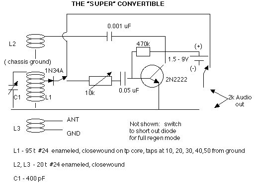
receiver that will blow your sox off. First, let's look at the schematic:
Some notes on parts, construction, and operating:
Most parts values are not critical. There is a balance between number of tickler coil turns, distance from tickler to tuning coil, and the tickler capacitor. This particular setup worked for me, but don't think of it as gospel. I also tried other combinations with good results. The 10k pot is a good regen control, but you want a larger value if you want to use it as a headphone amp volume control. My breadboard version used a 1 Megohm pot, and it also worked fine. I also varied turns and distance and the tickler cap value. Similarly, parts values for the basic amp, including the transistor, bias resistor, and input capacitor aren't fixed in stone. This set worked nicely, including in regeneration, with a very used 1.5 volt AA battery. Power consumption is zilch , less than a milliwatt with 4.5 V supply (a worn out 9 V battery)- use a used battery. If you use a PNP transistor, reverse the battery connections. Oh yeah, when I used a new 9V battery, the howling just wouldn't quit, and I ended up cutting the turns on the tickler coil, L2, to 5 turns before it behaved without pulling the coil way far away from the tuning coil. Just about anything you change will affect the oscillation of a regenny, including supply voltage. I am sure different transistors may require some slight modifications as well.
Since I use a metal flashing front panel on my little sets, I experienced some hand capacitance effects until I connected the chassis ground to the panel.
I used two of the 200 pF polyfilm variable capacitors in parallel for tuning capacitors, and got some bandspread out of it, and needed it. If your capacitors have any backlash, that is, the capacitance moves back in the direction from which you were coming when you remove your hand from the knob, this set will let you know, so use caps that are well worn in and not sticking.
I quit trying to get it to regenerate with the usual 47kohm resistor/crystal earplug combination, and put the phones across the 1k side of a little audio output transformer instead, which worked after I increased the tickler capacitor to 0.002 uF. If you have a set of 2k headphones which you haven't been using with your crystal sets 'cuz they are not sensitive enough, this circuit will bring them back into service. Taking a note from Anthony Felino, I used a 2k resistor in place of the usual 47k across the crystal earplug, and it worked fine with no additional modification; that saves you a transformer (expensive).
If it doesn't oscillate at first, reverse the connections to the tickler coil.
The 0.001 capacitor can be at either end of the coil. I was able to use a variable capacitor in its place and use it as a regeneration control, but why bother with the added expense? Besides, I was going for simplicity (I don't like building what I don't understand), and low cost.
You can eliminate the diode and build it as a straight regen, and get rid of some switching. Incidentally, you can wire this thing together just about any way you like. My prototype version used up almost every alligator clip lead I had in the shack, and worked fine. It doesn't have to be pretty.
As with any simple set, a good antenna and ground make a difference. An antenna tuner wouldn't hurt either, particularly with short antennas. It does like the strong locals, so you ought to have a trap handy to step on them; otherwise, you will get very familiar with the characteristic regen howl when you are trying to separate a weak station from a strong local. A bonus for those of you plagued by the HF ghosts at night is that when you are near the oscillation point, they disappear, since only the frequency of interest is being fed back.
When using it as a straight regenerative receiver, using a tap higher than the tap 10 turns from circuit ground caused the maximum operating frequency to shift down - tapping the top of the coil shifted the tuning down to almost 800 kHz. This drove me nuts until I tried the 10 turn tap. If you are working in the low end of the band, where your antenna is usually least resonant, using a higher tap will get you a little more signal strength.
The antenna and tickler coils on my rig can be moved closer to or further from the tuning coil. You should make provision for this as well. On the other hand, with a 6 foot antenna connected directly to the top of the tuning coil, you can do without the loading coil and still get the locals. Add a ground directly to chassis ground and you can do even better.
For my daughter's radio, I just left the diode in all the time, with no provision to cut it out. With a fair antenna and a poor ground, it is a hot, well behaved set. I did put a selector switch for using either a 10 turn or a 30 turn detector tap.
If you want a straight regen, you can
eliminate the diode and attendant switching. To save winding a separate
tickler coil, you can just wind your tuning coil about 10 percent longer,
and hook it up like this setup:
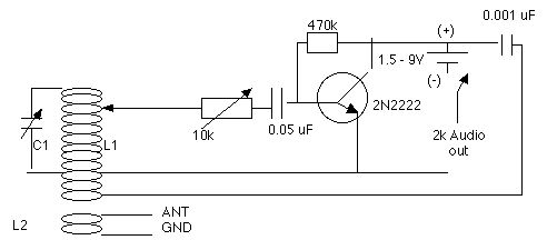
The chassis ground is connected near the bottom of the coil at the location where it would normally have been before the extra turns were wound on, and you don't have to worry if the tickler is connected correctly. You can even eliminate the switch and either remove the phones or the battery to turn it off. I tried this with an old oatbox radio coil I had laying about, and it worked pretty well. If you are winding a coil to make this, you should probably separate the tickler turns from the main tuning turns by a quarter inch or so. Heck, you can probably use the same value capacitor for the 0.05 and 0.001 - I tried two 0.05 caps and it still worked. Even without L2, I noticed that I could still get my two closest locals. With a bigger coil, you city boys could probably operate this without an antenna or ground. Neat, huh? This could be the basis for a large loop receiver. Just try to keep the leads short and the rig mechanically stable as much as possible. Even with the loop receiver, you probably would be advised to connect the chassis ground to an earth ground to reduce that hand capacitance effect.
Either of these little rigs can be used as a poor man's rf signal generator, and use it as a piece of test equipment. If that's all you want to do with it, replace the phones with a 2k resistor. Also, you don't need to attach an antenna to it. With a little care in construction, it will be pretty stable on frequency.
All in all, this was a fun little set to finally build and get operating. If you have never built a tube or transistor set from scratch, this is a good project. I'll include a picture of mine when my "photographer" gets back in the office.
And now, if the stuff above seems to complicated, go here to see an even simpler regenerative radio.