|
A Zero Loss, Unilateral 'Ideal
By Ben H. Tongue
Quick Summary: A device is
described that works the same as an audio transformer when connected between
the output of a diode detector and headphones, but it has several differences.
(1) No power loss. (2) Input and output resistances can be varied
over a wide range by selector switches. Its purpose is to enable
experimentation to determine the optimum impedance transformation for a
real world transformer when experimenting with different diodes and headphones.
It also has a switcheable 20 dB amplifier to enable better reading of very
weak signals.
1. What's it good for? Consider a crystal set that uses an audio transformer. One can determine what its performance would be if the transformer had no loss and provided an optimum impedance match between the output resistance of the diode detector and the headphone load.
One of the problems one encounters when designing a high performance crystal set is determining the optimum parameters for the detector-to-headphone audio coupling transformer. Its impedance transformation ratio is the main factor to be considered, though the inherent loss is also important. Another factor is the primary and secondary impedance levels for which the transformer was designed, compared with the levels to be used in its crystal set application. Consider the performance of two transformers having the same transformation
ratio, but designed to operate at different impedance levels. They
will not perform the same. To illustrate this point we will consider
a transformer designed to transform a 10,000 Ohm source to a 90,000 Ohm
load. This could be an AES PT-157, PT-156, Stancor A-53C or similar
transformer originally designed to couple the output of a first audio stage
to push-pull grids. If the designer did a good job, this transformer
will have the lowest possible loss consistent with its specified frequency
range, power handling capability and cost goals. If it were to be
driven from a 40,000 Ohm source and loaded with a 380,000 Ohm load (still
a 1:9 impedance ratio), its center-band power insertion loss will be increased
and the low frequency end of the band will be rolled off. The reason
for the increase of center-band loss is that the equivalent shunt resistance
caused by losses in the iron core load down the now higher source resistance
(40,000 Ohms) thus increasing loss. The shunt inductive reactance
of the primary winding, at the low end of the band loads down the now higher
source resistance (40,000 Ohms) more than before, thus increasing the roll-off
at the low frequency end of the audio band. The high end of the audio
band will also probably be rolled off because the reactance of the equivalent
shunt capacitance of the primary winding will cause more loss when being
driven by a 40,000 Ohm source than one of 10,000 Ohms. On the other
hand, if the transformer was driven from a 2,500 Ohm source and fed a 22,500
Ohm load, center-band power insertion loss will still be increased.
The reason is the ratio of the source resistance to the series resistance
of the primary winding is not as high as when the source was 10,000 Ohms.
More of the input power will get dissipated in this series resistance and
less transferred to the secondary. A similar loss effect from the
winding resistance occurs in the secondary. The low frequency end
of the band will reach to lower frequencies than before, but the high end
may get some roll-off due to leakage inductance in the primary and secondary
windings. One can think of this effect by visualizing a parasitic
inductor in series with the primary and secondary windings.
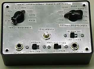
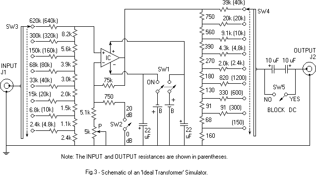
4. The Unilateral 'Ideal Transformer' Simulator. How should one proceed in determining the Specifications for a transformer that will provide optimum performance in the crystal set? One may not know the audio source resistance of the diode detector, or even the average impedance of the headphones load. The UITS can be used to find these two values. It also has a 20 dB gain switch option that can be used to enable reception of very weak signals as well as a switch to block DC from the phones, if desired. There are two operating adjustments. One sets the input resistance Ri, the other the output resistance Ro. These two settings don't interact since the device is unilateral. The equivalent transformer turns ratio is the square root of the ratio of the two resistance settings. Here are some ways that the UITS can be used:
Note. The parallel RC (see Article #5) needed in series with the primary
of an actual transformer is not needed with the UITS because its input
resistance is the same for DC as AC.
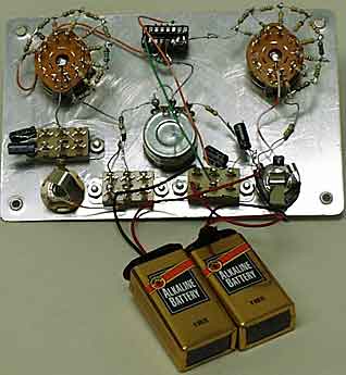
Some component specifics:
Calibration is simple. Set SW2 to the 0 dB position, SW3 and SW4 to their 10k Ohm settings and potentiometer P for zero gain. To do this, load J2 with a 10k Ohm resistor and feed a 1 kHz signal from an audio generator into J1. Adjust P so that the output voltage at J2 equals the voltage at J1. Use an audio generator and DVM to read the voltage at P. If no audio generator is available, connect the output of the crystal set diode detector (no audio transformer used) to J1 and a headphone set of about 10k Ohm impedance (2k Ohm DC resistance) to J2. Tune in a station and adjust potentiometer P so that the volume is the same as when the detector output feeds the headphones directly. This setting does not have to be changed in the future. Note: Connect the output of the crystal set detector to the ITS with as short a length of cable as possible in order to minimize added shunt capacity. If the tone quality of the signal changes from one resistance setting of SW3 to another, the shunt capacity in the detector output circuit is too high. This can be caused by using a bypass capacitor or an interconnecting cable of too high a shunt capacity for the resistance setting of SW3. I use an eighteen inch length of RG-59 type coax for my cable. It has a capacitance of about 20 pF per foot. The performance of magnetic diaphragm type headphones can be affected by the DC current passing through them when no coupling transformer is used. SW5 is provided for those who choose to block the DC. Published: 01/05/01; Last revision: 04/14/01 |