|
Directivity of the "Inverted" L Antenna, with Speculation as to why it Occurs and How to Enhance it. by Ben H. Tongue
Dieter Billinger (sky_wave_99), on Yahoo's "The Crystal Set Radio Club"
has reported that when he changed the orientation of his inverted L antenna
from pointing south (open end) to pointing west, he picked up more AM stations
and DX in the westerly direction on his crystal radio. He believes
that this illustrates a directivity characteristic in the inverted L antenna.
I note that his indication of the direction of greatest pickup is the same
as that of a Beverage wave antenna. A Beverage antenna is like the
inverted L, except that it is between one-half and several wavelengths
long, about 15 feet above the ground and terminated by a resistor at its
open end. Terman, in his "Radio Engineer's Handbook" gives an explanation
of how the Beverage works. I have given some thought as to why the
inverted L might exhibit directional characteristics for the reception
of ground (vertically polarized) waves, and present some ideas here.
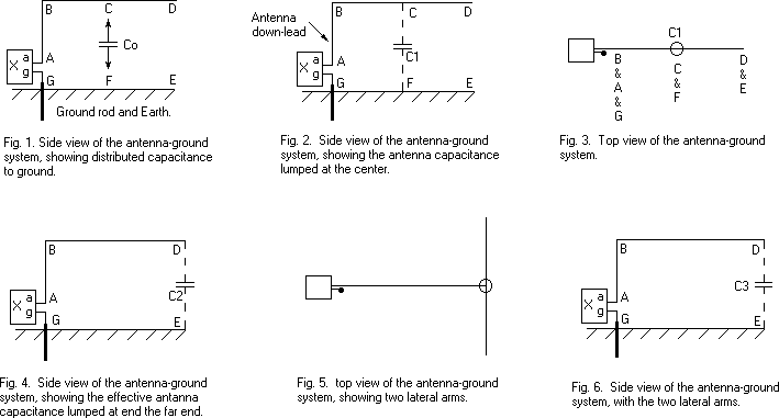
First off, understand that I am not an antenna engineer and present these speculations to suggest a way to increase the directive gain of a small (compared to a 1/4 wavelength) antenna for DX work. We will consider that the operation of an inverted L antenna results from the sum (superposition) of two modes of operation. One is the "tophat" capacitively loaded vertical antenna. See Fig. 1. The total capacitance, Co of wire BD to ground acts as the top hat capacitance for the "vertical antenna", downlead BA. This is an omni-directional antenna. The second is a single turn 'loop' antenna. Let X represent a crystal radio set with antenna and ground connections, a and g. Fig. 2 shows Co as a lumped capacitor C1, connected to ground at the center of the BD. The rectangular loop circuit ABCFG, consisting of the four sides AB, BC, CF and FG can be looked at as a single turn loop antenna of area A, oriented to pickup signals from the B<->D direction. Note that the path for the 'displacement current' through C1 makes up one side of the loop. The current flowing from the induced EMF in the loop will combine to current from the EMF picked up in the down lead BA. Apparently these two EMF's add when a signal comes from the direction to which the open end points and tend to cancel when coming from the opposite direction. This gives a plausible explanation of the mild directivity of the inverted L antenna. This directivity has been theoretically demonstrated by using computer simulation. For clarity, Fig. 3 shows a top view of the antenna. The following changes to the configuration may serve to increase the directional gain of the antenna (I haven't tried them out.). The induced voltage in a loop antenna (small compared to a wavelength) is proportional to its area. If the effective location of capacitor C1 could be moved to point D, and its value kept the same, the area of the loop would be doubled to 2*A (ABDEG), thus doubling the current from its induced EMF and further increasing the directive antenna gain. Let us change the lumped representation of Co as one capacitor C1 into two capacitors, one from point B to ground and the other from point D to ground. They will each be equal to one-half of Co and both still will act as a top-tat capacitor for the vertical antenna BA, otherwise known as the lead in. The one from D to ground will be called C2. See Fig. 4. One way to add more capacitance to ground at point D is to construct two lateral arms on the antenna. See Fig. 5. If each arm is the same length as one half the antenna BD (They can be of some other length.), the effective capacitance they add at point D is 2*Co/2 = Cadded. The sum of the two capacitors C2 and Cadded is 1.5*Co = C4. The loop area is doubled and the current from the induced EMF is tripled (because C3 is one and one half times C1). The antenna directivity may thus be increased giving more gain in the direction in which the two effects add, and less in the opposite direction. If the directive effect can be made strong enough, a cardioid pattern should result, with a good null in the "opposite" direction. A more practical approach might be to have the two side arms droop down at an angle and be secured to ground with insulated guy wires. A single vertical wire, similar to the lead-in, might work as a substitute for the two arms if its bottom end does not get too near the ground. Published: 07/29/00; Last revision: 08/03/00 |
