|
An Explanation of how the "Mystery Crystal Set" Works By Ben H. Tongue
Quick summary: Plans for a crystal
radio called the "Mystery Crystal Set" were published in the newspaper
"The Sunday Mail" of Brisbane, Australian in 1932. The "Mystery"
in the name comes from the fact that, in the schematic, there seems to
be no ground return to which the antenna currents can flow. The design
was used by entrant Ray Creighton in the "Crystal Set Competition" held
on March 19 2000 by the Southeast Queensland Group of the Historical Radio
Society of Australia in Malaney, Australia . His entry won first
prize in one category and third prize in another. see
it here The design has recently become popular in the
US as shown by the many messages posted on the Yahoo! Clubs site "thecrystalsetradioclub".
On 6/6/2000, in messages 2172 and 2173, I posted the following explanation
(edited here) of how I believe the Mystery Set works:
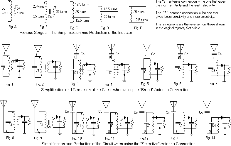
Two assumptions made in the analysis: They are that the distributed
capacity between the two coil windings can be represented by one lumped
capacitor Cc, that is connected between the centre of one winding to the
centre of the other. See Fig. B. The other is that the coupling
between the primary and secondary windings is unity. This assumption
is very close to reality for the bifilar wound portion of the transformer.
It is not as close for coupling between the non-bifilar wound parts and
the bifilar part. This does not affect the validity of the analysis.
Keep in mind that in transformers with unity coupling, the ratio of the
voltage on any winding to any other is directly proportional to the number
of turns on each winding. This also applies to a portion of one winding.
(Just use the number of turns in that portion.) Figures A through
E show the inductive circuit through various changes as the following reduction
and simplification proceeds.
Simplification and reduction of the circuit of the Mystery crystal set using the "Broad" non-earthy antenna connection: The physical circuit of the Mystery set is shown in Fig. 1 with the
antenna connected to the non-earthy side of the primary. The dots
on the windings show the start of each winding, assuming that they are
both wound in the same direction. Figure 2 shows a coupling capacitor
Cc, between the two windings. It represents the distributed capacity between
the primary and secondary windings. Cc is in a series circuit with
the antenna and ground. Fig. 3 shows it shifted up to the antenna
and out of the way. No change in performance will result. The
top and bottom leads of the secondary are connected (each 12.5 turns from
the centre), to the corresponding points on the primary (12.5 turns up
and down from the centre). This is shown in Fig. 4. Since the
two top points have the same AC voltage on them, no current will flow through
their connection and the circuit operation will be undisturbed. The
same goes for the bottom connection. Figure 5 shows the resulting
equivalent circuit. Since all portions of the winding are assumed
to be unity-coupled to each other, performance will not change if the tuning
capacitor C1 is connected as shown in Fig. 6, as long as its value is changed
appropriately. C1 is connected across 50 turns of the inductor.
C2 is connected across 37.5 turns. The inductances of a unity coupled 1:1
transformer are directly proportional to the square of the number of turns.
The number of turns across which C2 is connected is 3/4 of the number of
turns turns across which C1 is connected, therefore, the inductance across
which C2 is connected will be 9/16 the inductance across which C1 is connected.
C2 should be increeeased from the the value of C1 for the circuit to work the same.
The bottom portion of the coil in Fig. 6 can be eliminated since nothing
is connected to it. The final result is the equivalent circuit shown
in Fig. 7. Here we see a conventional crystal set circuit with the
antenna-ground components connected directly across the full tank, with
isolation from full antenna loading supplied by the capacitor Cc.
The detector load is tapped in at 2/3 of the tank voltage to reduce its
loading effect on the tuned circuit. That's it for the non-earthy
"Broad" antenna connection.
Simplification and reduction of the circuit of the Mystery crystal set using the "Selective" earthy connection. Figures 8 through 14 show the simplification and reduction of this circuit.
It proceeds in an manner similar to the one for the "Broad" connection.
Now look at Fig. 14. The value of Cc is unchanged from that in Fig. 7.
C4 will have to be somewhat larger than C3 was for the circuit to work the
same . The antenna-ground components and Cc are now connected
across only 1/3 of the tank instead of the full tank. The detector
load is still tapped in at 2/3 of the tank voltage. That's it for
the earthy "Selective" antenna connection.
Conclusion: When using the "Broad" antenna connection, the antenna-ground components are connected through Cc across the full tank. This arrangement puts a certain amount of antenna resistive loading on the tank. The loading results in specific sensitivity and selectivity characteristics depending on the diode load, value of Cc, unloaded tank Q, L/C ratio and antenna characteristics. See Fig. 7. When using the "Selective" antenna connection, the antenna-ground components are connected through Cc across only 1/3 of the tank coil turns. This results in a reduction to at least 1/9 of the resistive loading by the antenna on the tank, compared to the loading in the "Broad" connection. See Fig. 14. The reduced loading increases loaded circuit Q, and hence selectivity. The ratio of unloaded to loaded Q is reduced, increasing circuit loss and reducing sensitivity. Published 08/11/01; Revised 08/12/01 |
