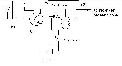
When you are digging around in old magazines and texts, one of the things that always gets me is when components are (1) no longer available (2) listed with part numbers that you know you'll never find, and (3) not specified as to value (a common problem in texts). So, doing the best I could, I picked this design and arrangement out of an assortment of ideas from at least two continents, and here is the result:
As with most of my stuff, I didn't try to optimize this circuit, primarily because I really don't have the talent, equipment, skill, or patience. I did, however, try a variety of values for C1 and C3 between 100pF and .05 uF, and they were all "acceptable". Likewise, I went from 22k to 470k for the resistor they all worked pretty well too. My wiring was plug ugly too, with alligator clips and parts strung out all over the table.
I suspect that if you clean this up and even put a tuned network between this signal booster and the antenna, and then gang the variable capacitors, you might improve the selectivity a bit and be on your way to making a tuned radio frequency (TRF) receiver.
If you are using this amp to inductively couple to the set, as to a superhet portable, then make sure you connect the ground connection to a ground of some sort. Same goes to hooking it up to a crystal set; the ground needs to be used.
25 Nov 00 Okay, so I decided to make this
thing "right" and see what it was capable of doing. I made a few
changes in the components, such as using 0.001 uF capacitors for C1 and
C3 (not intentional - just misread the directions - hi), and using a 220
pF variable capacitor and a 400 uH ferrite core coil for the tank circuit.
Didn't bother with the bypass feature either. I used an old 1.5 v
battery. Anyway, I hooked it up to where I usually connect
the antenna on my xtal sets, and started playing around. Here are
some results:
a. Gave 15-20 dB gain
when used with a 6 foot antenna (that's gain over the antenna by itself).
My best estimate is that this is what 25 to 30 feet of wire out the window
would give you, since it didn't get the levels up to my 50 footer.
b. When input with a 50
foot antenna, signals went up, but so did noise, a bunch. Didn't
try much with the longer antenna after that. I suspect you might find some
transistors less noisy than others.
c. Using a 6 foot antenna,
I fed the amp output to a "tuggle" antenna tuner. Best results were
achieved when I put it to a tap near the center of the tuner coil.
When I changed taps, this also required me to adjust the tuner capacitor(s).
d. Varying the tuning
capacitor of the amp didn't seem to make much difference anywhere in the
am band. When I removed the core from the coil, output dropped by
about 35 %. Could probably replace the variable with a fixed capacitor
of about 200 pF, and do the same with the inductor, probably getting away
with one of those small low Q babies of about 150 uH to put it in the middle
of the band somewhere; the set seems pretty broadband, and gain was pretty
much the same across the band.
e. With the amp just connected
to the 6 foot wire and ground, putting my pocket portable within a couple
of inches of the coil cleaned up weak noisy daytime signals. Near
my MK484 "dx" set, it brought some stations in that were otherwise inaudible.
Again, I didn't try to go overboard on this one, since my primary emphasis is on enhancing the operation of a basic crystal set, and keeping my circuits simple and cheap. This circuit seemed to give almost as much signal boost as did the circuit in the Convertible. Be advised that you might not get very good results with this, and it seems that an antenna longer than a few feet doesn't help, but I still wonder about an antenna tuner in front of it.... One transistor type I tried was super noisy. Playing around with the bias resistor may be needed. You might even consider using a link wound around the coil of the tank circuit to feed the crystal set.
![]()