----------------
This AM radio circuit will demonstrate how a radio wave is received and detected, using a very simple tuned radio frequency design. (TRF)
Radio signals
-------------
A radio wave is a complex signal that contains the carrier frequency of the broadcast station and the audio output of the microphone or audio amplifier source. It begins with the RF oscillator circuit, which is in affect a signal generator that is tuned to the precise operating frequency of that particular station. The generator output is applied to the final output stage of the transmitter, made up of several tuned tank circuits.
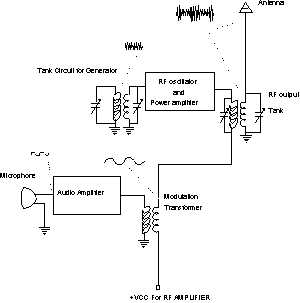
The block diagram below shows how the oscillator and tank circuit are connected to the broadcast antenna where the signal is radiated into the atmosphere over long distances. Before it is broadcast, the audio signal is modulated with the RF carrier so that it becomes part of the transmitted signal. In AM broadcast, this is done by changing the amplitude of the RF carrier signal with a circuit called the MODULATOR. A modulator is a circuit that combines two signal together to form one signal, but the characteristic's of both are retained. This means that a modulated radio wave contains the carrier frequency and the audio signal when it is transmitted. The transmitted signal can than travel over thousands of miles to a radio receiver.
Referring to the diagram, you can see that the audio signal is connected in such a way as to change the voltage level or the amplitude of the radio frequency sine wave. This signal contains the frequency of the transmitter and it's amplitude is changing at the audio rate of the audio circuit. If a radio station has a broadcast frequency of 1080 on the dial, then the frequency of the oscillator is set to 1.080 mhz (the reading on the dial is in Khz) so if you were to view this signal on the o'scope it would appear as a 1.080 mhz sine wave with changing amplitude.
Radio receiver
---------------
The function of the radio receiver is to recover the audio signal that was modulated onto the RF carrier at the radio station, and apply it to the speaker, reproducing the sounds of the announcer. The source of the radio signal starts at the receiver antenna, which is a length of wire exposed to the atmosphere. When the RF energy passes by the wire, a small voltage and current will be induced that will change in step with the RF energy striking it. RF energy will induce voltage and current in any kind of conductor that gets in it's path, that is why a radio won't work well when inside a steel building. (The radio waves will be absorbed by the steel) The other end of the antenna is connected to a tank circuit inside the radio and it is tuned to only one resonance frequency. Even though there are hundreds of radio stations transmitting signals at the same time and they are all hitting the antenna inducing currents, only one of them will cause enough current to be of any use. The tank circuit used in this radio is a series connected tank, which means the current will be maximum at the resonance frequency. If we make one of the reactance's variable, we can select or tune any one of the stations passing by the antenna wire by adjusting the reactance to a new resonance frequency.
This circuit uses a variable capacitor but you can use a variable
coil as well. Scope trace 1 in the diagram shows what the signal at this point will look like if viewed with a good quality scope and a strong station.
Scope trace 1 also shows how the audio looks that is added to the RF signal. Notice how the amplitude of the sine wave is changing and if you connected all the peaks of the sine wave together, you will see another sine wave of a much lower frequency. From this you should see that audio is "riding on top of the RF". You will also see a cancellation of the audio signal because there is a opposite peak for each peak of audio. To see this even further, draw a horizontal line through trace 1 at the middle.
This cancellation of the audio means that it will have no effect on the circuit and there will be Zero power level caused from the audio portion of the signal and in order to be of any use to our circuit, it must be DEMODULATED or recovered.
The demodulator circuit is made up of the 1n34 germanium diode and the .01 ufd. capacitor on the output of the diode. The diode can only conduct current in one direction and it must have a voltage that exceeds 300 millivolts. The signal from the tuned tank circuit is connected directly to the anode of the diode so that any positive voltage applied to it will cause current flow.(if > 300mv) The output of the diode will be only half of the RF signal as shown in scope trace 2 on the schematic. Since we are only interested in the audio signal, the hi frequency portion of the signal is shunted to ground through the .01 cap. This capacitor and the resistance of the diode/tank circuit form a low pass type filter allowing only the lower frequency audio signals to pass through the circuit and on to the audio amplifier.
Details of the circuit operation
--------------------------------
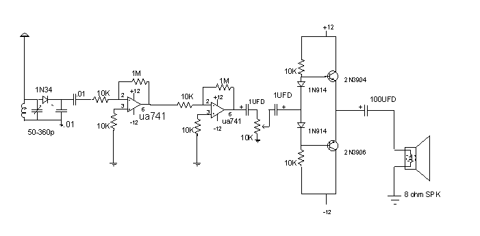
The TRF radio shown in the block diagram and the schematic diagram, is made up of several different circuits that each perform a separate function in the processing of the radio signal. The circuit or stage names are:
1. RF stage
Radio Frequency. This circuit is made up of L1 and C1 connected in a series connected resonant tank circuit that is used to select one radio station out of many that are causing current in the circuit at any one time. Although the circuit looks like a parallel connected tank, it is indeed a series connected tank. The reason for this is the fact that the voltage source (RF energy) is inducing a voltage and current inside the coil windings and must appear as an internal voltage. This internal voltage is then in series with the coil and the capacitor thus making it a series tank. In a series resonant tank circuit, the current is maximum at resonant and the voltage developed across the reactance (Xl and Xc) is much higher then the applied voltage.(resonant step up effect) The output of the tank, which is being applied to the detector stage, is across the tank capacitor C1. C1 in this circuit is a variable capacitor that changes capacitance as the shaft is rotated. When the capacitance changes so does the resonant frequency of the circuit. If for example, 200 radio stations are passing by the antenna and inducing currents into the circuit, only one of them will be of the same frequency as the tank circuit therefore producing the most current. It is the radio station that has the same frequency as the tank that will be received by the circuit. To change radio stations on the radio all we have to do is change the capacity of the tank and the resonant frequency.
The signal developed across the tank can be viewed with a general purpose o'scope connected across C1. When you have the receiver working, tune in WTIC on the dial. This station transmits on a frequency of 1.080 mhz + or - .0001 percent. This is called the carrier signal of the radio station and is a pure sine wave type signal. If the scope is adjusted properly you should see a very good sine wave across the cap. You will notice however, that the amplitude is changing as the audio changes, this is because of it being an AM (amplitude modulated) type radio station. After you observe the carrier signal, turn the Horz. sweep rate down and observe the audio signal that is "riding on top" of the carried. The signal should look like scope trace 1 on the schematic diagram.
The tuning range of the radio and of the tank is determined by the values of the inductor L1 and the capacitor C1. The inductor L1 has a fixed inductance of 250uh and the variable capacitor has a capacitance range of 10pf to 360 pf. The highest frequency that can be tuned will occur when C1 is adjusted to it's minimum capacitance of 10pf. The lowest frequency that can be tuned will occur when C1 is adjusted to it's maximum capacitance of 360pf. This range of capacitance should provide a tuning range of 550khz to 1.6mhz, which is the entire AM broadcast band. (calculate the range to verify this)
2. Detector Stage --------------
The Purpose of the detector stage is to recover the audio signal from the RF carrier and pass it on to the audio amplifier stage. This circuit uses a germanium diode (1N34) D1 as a half wave rectifier, that only conducts when the anode has a positive potential of approx. 300mv. Referring to the schematic, you can see that the output of the tank is connected directly to the anode of the diode. When a strong radio station is tuned in by the RF stage, the signal level will exceed the necessary voltage to for the diode to conduct. The output or the cathode side of the rectifier will have only half of the radio signal, which should look like scope trace 3 and 4 on the diagram. The voltage at this point contains only the audio signal portion of the radio wave. The carrier frequency, which is very high compared to the audio signal, is shunted to ground through the RF bypass cap. C2.
C2 in conjunction with C3, form a low pass type filter that passes the low frequency audio signal to the input of the audio amplifier and shorts or shunts the frequency RF to ground.


---------------
The audio amplifier circuit contains two general purpose op-amp IC chips, UA741 that provide a very high gain voltage amplifier stage. IC1 is used as the 1st AF amplifier stage and has a gain of Av 1 = 100. The op-amp is a very stable circuit because the characteristic's of the circuit are determined by the external resistors and not the op-amp itself. Voltage gain is determined by the ratio of R2/R1. To increase or decrease the gain of the circuit you can change either R2 or R1.
The second AF amplifier stage is made up of a second UA741 with the same components for a voltage gain of Av2 = 100. The total gain of both the 1st and 2nd stage is equal to the product or Av1 x Av2, for a total of 10,000.