MAGNETIC MOMENTS, Number 7
ELECTROMAGNETIC NOISE - NATURAL SOURCES OF NOISE
(originally printed in Speleonics 9, Spring 1988)By Ian Drummond
Previous "Magnetic Moments" have dealt with items affecting the strength of the transmitted signal from a loop antenna. Equally important in determining the performance of a cave radio system is the electromagnetic (EM) noise present at the receiver. The ratio of the power of the signal to the noise power (S/N, the signal-to-noise ratio) presented to the ear of the listener determines if the signal can be heard and if it can be understood.
A pulsed tone of the type used in cave radios, can be recognized 50% of the time at an S/N of 6dB (1). For voice communication much higher S/N ratios are required.
EM noise can originate within the radio receiver, or it can be external in origin. The external noise can be further classified into man-made, and natural noise. Man-made sources include deliberate transmissions such as navigation systems and broadcasts, and incidental RF emissions from motors, electric fences, power systems and a myriad other sources. The incidental man-made noise can be very intense in areas of high activity but fortunately it is often (like cave-radios!) very local in nature and the intensity drops rapidly away from urban or industrial areas.
In the frequency range of cave radios (2 - 200 kHz), atmospheric noise is a very important factor and the predominant source is lightning from thunderstorms. The storms need not be local, the EM energy propagates over thousands of kilometers. People are suitably impressed when I tell them that the performance of my cave radio is limited by thunderstorms in the tropics, and it may be true!
The best general source of information on natural noise seems to be CCIR Report #322, Geneva, 1963. While I have not seen the report itself, I have found a set of 24 world noise-contour maps in Saveskie's book (2) and further good information on using this data in a reference book published by Sams (3).
Noise levels vary with time of day and season of the year. Therefore the day is split into 6 four-hour periods and the year is divided into the four seasons, giving a total of 24 time periods, each with a map and two associated graphs. An example of one map is shown here for the summer period between noon and 4:00pm.
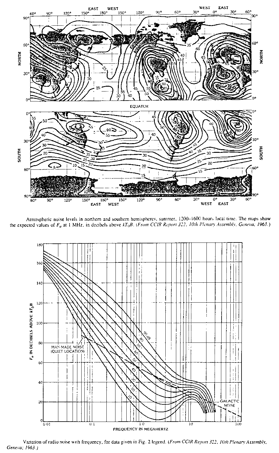
The procedure to use these maps and graphs is as follows:
- Find your location on the map and read the nearest contour line. Alberta is at 55 N, 115 W. The value is 40dB.
- Go to the graph associated with each map. Locate the frequency of interest (115kHz) and find its intersection with the line marked "40". Read the Y-axis value of F (95dB above kTb).
- Convert this value to the magnetic field strength using the following formula:
- The field strength must then be adjusted for the desired bandwidth using the formula:
- Finally the field strength can be expressed in microA/m using the conversion:
Hn = F + 20 log10f(MHz) - 117.0
| where: Hn = | RMS noise field strength in a 1kHz bandwidth in decibels above 1 microA/m. |
| F = | noise value in decibels above kTb |
| f = | frequency in megahertz |
In this example, Hn = -41dB(1microA/m).
H = Hn + 10log10(bandwidth(kHz))
For the ASS voice radio, the bandwidth is 1.5kHz,
so H = -39dB(1microA/m)
H(microA/m) = 10(H/20)
In this example the noise field strength is 0.011 microamps/metre.
The remaining graph associated with each noise map (which is not shown here) gives the standard deviation of the RMS noise value, and the ratio of the first and ninth decile to the RMS value.
Knowing the atmospheric noise at a location, the maximum range of a cave radio can be estimated. If a signal-to-noise ratio of 10dB is required at the receiver and the atmospheric noise is -39dB(1m A/m), then the signal must be -29dB or 0.035uA/m.
The antenna used normally with the ASS cave radio (0.7 m square) has a magnetic moment (NIA) of 11 A.m2.
As noted in Magnetic Moments #1, H = NIA.G / 2 d3, where d is the range, and G is the attenuation factor.
As G is a function of d, exact solution of this equation is not easy (or necessary). Assuming G is 0.3 (corresponding to 3 skin-depths), then d is approximately 240 m.
The ASS radio has achieved voice communication at depths over 200 m, with these antennas, in the summer in Alberta, suggesting that there are no major shortcomings in the receiver. Also suggesting that there will not be any more dramatic increases in range through refinements in the current SSB equipment operating at these frequencies.
References
- R.J.Urick, Principles of underwater sound for engineers. quoted in US Bureau of mine IC8907, Post-disaster Survival & Rescue. 1975.
- P.N.Saveskie, Radio Propagation Handbook, Tab Books, Blue Ridge Summit, Pa,17214, USA.
- Reference Data for Engineers, 7th ed. H.W.Sams & Co. (Macmillan & Co), Indianapolis, IN, 46268, USA
Return to the Top of the Page
Copyright © 2000 Communications & Electronics Section of the NSS, Inc. - All Rights Reserved.