MAGNETIC MOMENTS, Number 9
GROUND CONDUCTIVITY
BY ELECTRO-MAGNETIC (EM) METHODS
(originally printed in Speleonics 12, Apr 1989, p4-5)
By Ian Drummond
Since the editorial in Speleonics 8 about searching for caves by measuring ground conductivity, I have had some correspondence with cavers doing just that. Also the second newsletter of the British Cave Research Assoc. (BCRA) cave radio group has an article on conductivity (or resistivity) techniques. (Speleonics 11, p1 has an announcement on the BCRA newsletter).
Both groups were concerned with the traditional current injection method, where an array of 4 electrodes are inserted in the ground, an electrical current (AC usually, but DC can be used) is injected via 2 electrodes and the voltage is measured across the other two.
As discussed in the Speleonics 8 editorial, EM methods of measuring conductivity appear to offer some significant advantages by increasing speed of measurement in the field. This issue of Magnetic Moments will look at some of the principles underlying EM methods, and suggest a particular scheme which looks easy to implement with existing cave radio equipment.
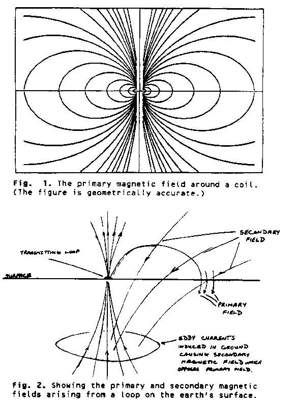
First consider a transmitting loop lying flat on the ground, (Fig 1). The primary magnetic field is the familiar shape shown in the figure, however the current in the coil will induce eddy currents in the conductive ground. These eddy currents will, like those in any inductive load, be 90o out-of-phase behind the current in the primary coil, and will give rise to a secondary magnetic field (figure 2).
Consider then the magnetic field at a point on the surface to one side of the transmitting loop. It consists of two components, the vertical primary field, and a secondary field which has both vertical and horizontal components and is 90o out-of-phase with the primary field.
J.R.Wait has published equations describing the strength of the magnetic field in these circumstances. (Mutual electromagnetic coupling of loops over a homogeneous ground. Geophysics, Vol XX, #3, July 1955, pp. 630-637).
Given this basic information there are several ways to estimate the ground conductivity. Most straight-forwardly, using a calibrated transmitter and a calibrated receiver, the value of the mutual impedance can be measured from total field strength, to allow calculation of the conductivity.
Using more sophisticated equipment with a phase-locked receiver, the value of the secondary field only can be measured, allowing more discriminating estimation of the conductivity.
Both such methods (and others, for all I know) are in use in commercial equipment, as reported for instance, in "Geophysical Techniques for sensing buried wastes" Benson, Glaccum, and Noel; Report EPA-600/7-84-064. US Environmental Protection Agency.
Both methods are also difficult to implement with existing cave radio equipment, therefore I spent some time thinking about Wait's equations to see if his results could be adapted to use with cave-radios. The following method has not been tried practically, but seems to have a lot of promise.
(Editorís note; since publication of this article in 1989, Brian Pease has very successfully used closely related methods to measure ground conductivity).

The proposed method depends upon using two receiver antenna orientations and measuring the ratio of the signal strength. This eliminates calibration of the transmitter, and if the receiver output is linear with input signal, eliminates receiver calibration too.
The proposed procedure is as follows:
- Set-up the transmitter loop with its plane exactly horizontal on the surface of the ground above the point of interest.
- Set-up the receiver loop at a measured distance from the transmitter equal to the estimated depth of caves in the area. The loop should be set with its plane exactly horizontal, at the same elevation as the transmitter.
- Measure the signal strength (volts) with the transmitter off, V(H-background), and transmitting continuous tone, V(H).
- Rotate the receiver loop so the axis of the loop is horizontal and pointing directly at the transmitting loop.
- Measure the signal strength (volts) with the transmitter off, V(V-background), and transmitting continuous tone, V(V).
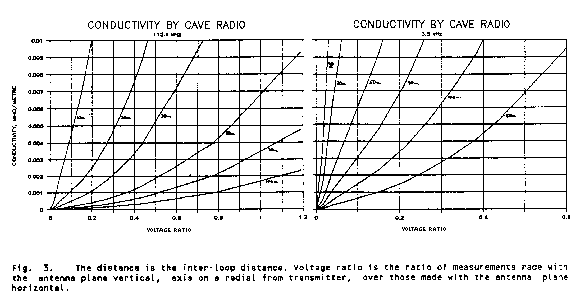
- Calculate (V(V) - V(V-background)) / (V(H) - V(H-background)) and use Graph 1 or 2 to lookup directly the value of the conductivity.
For those people using other values of frequency or inter-loop distance than given in the graphs, I have tabulated the Voltage Ratio against "Numerical Distance" and it will be necessary to calculate the conductivity from the formula given at the end of the table.
Table 1. Numerical Distance vs. Voltage Ratio
|
Num. Dist. |
Volt. Ratio |
Num. Dist. |
Volt. Ratio |
| 0.0 | 0.0 | 2.4 | 0.591 |
| 0.2 | 0.0159 | 2.6 | 0.647 |
| 0.4 | 0.0404 | 2.8 | 0.704 |
| 0.6 | 0.0872 | 3.0 | 0.771 |
| 0.8 | 0.151 | 3.2 | 0.819 |
| 1.0 | 0.211 | 3.4 | 0.866 |
| 1.2 | 0.269 | 3.6 | 0.912 |
| 1.4 | 0.326 | 3.8 | 0.963 |
| 1.6 | 0.383 | 4.0 | 1.013 |
| 1.8 | 0.437 | 4.2 | 1.067 |
| 2.0 | 0.483 | 4.4 | 1.127 |
| 2.2 | 0.533 | 4.6 | 1.189 |
|
| |||
Conductivity (mho/m) = (ND/d)2 . (1/f) . 1.27x10⁵
| where: ND = | Numerical Distance |
| d = | distance between loops (metres) |
| f = | frequency (Hz) |
I would strongly recommend when doing a traverse along a surface line, that readings be taken with the two antennas aligned with the traverse direction, and with the two antennas at right angle to the traverse direction. The reason for this is that I feel limestone terrain will exhibit different conductivity in different horizontal directions (anisotropy). This could be caused by joints, but also by caves, and indeed I have experienced directional effects with my cave radio that I cannot explain except by anisotropic conductivity of the ground. (See Speleonics 9, page 8).
This observation applies equally to conductivity surveys done by current injection methods.

Further Work.
Obviously there are a lot of practical things which could be tried to see how such an EM system would work. There is however one major theoretical contribution which would be very useful if there is a person out there who has a computer and the necessary knowledge and skill.
The interpretation of the conductivity estimates is very primitive, simply assignment of a "bulk value" to a point in the ground half-way between the loops at a depth equal to their separation.
It seems to me it should be possible to construct a numeric model so that the effect of various sub-surface conditions could be tested. Chambers, joints, bedding-planes, and tubes would all affect the apparent conductivity measured from the surface in different ways. Such a model would also give an estimate of the sensitivity of the method, that is the smallest feature which might be detected under given conditions.
It would certainly enhance the interpretation of conductivity data.
Return to the Top of the Page
Copyright © 2000 Communications & Electronics Section of the NSS, Inc. - All Rights Reserved.