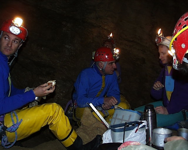
Graham NAYLOR, a physicist at the European Synchrotron in Grenoble, is a member of the Isere cave rescue team and works in collaboration with the ADRASEC 38 on the development of new cave communication systems. He is the third from the left.
Designed by Graham Naylor naylor@esrf.fr
Development and testing in collaboration with SSSI and ADRASEC 38
Graham NAYLOR, a physicist at the European
Synchrotron in Grenoble, is a member of the Isere cave rescue team
and works in collaboration with the ADRASEC 38 on the development of
new cave communication systems. He is the third from the
left.
He is explaining the operation of the system
NICOLA to gendarmes of the PGHM and to the Lieutenant ROMARY of the
technical department of the gendarmerie nationale at Rosny-sous-Bois
during test in the cuves de Sassenage (near Grenoble) with regards to
future use by the gendarmes of the PGHM.
Euro Norm : I-ETS 300 330 Class 3
Emission frequency : 86.95 Khz
Intermediate frequency : 455 Khz
Mixing and BFO : Derived from quartz oscuillator
Front-end filtering : Preselection with low pass filter and two stage LC filter
IF filters : Ceramic filter + high gain ampl + mechanical filter.
Modulation : Single side band.
Microphone: electret
Power into antenna : 3 Watts
Current loop : 0.1 A when matched
Adjustment : A 3 position switch to adapt the via the transformer the impedance of the ground to the impedance of the output stage.
Supply: 12V to 15V
Consumption at 12V : 0.06A on reception and 0.9A on emission
Antenna : Large virtual loop constituted by the two electrodes connected to earth spaced by 40-80m
Design : Mixed surface mount and through hole.
Performance : Through rock transmission 1200 m maximum dependant on the local geological conditions, 500 m generally useful.
Size : 150 X 80 X 50 mm
Weight : 0.250 Kg without batterries
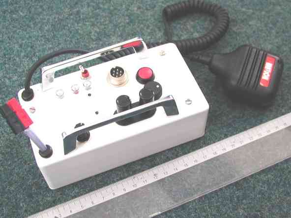
The unit is shown here housed in a protective box for use underground. It is recommended that it is transported in a seperate waterproof container to avoid excessive contamination with mud and water. The microphone is hard wired to avoid any problems with connectors, but a connector is provided to allow future expansion for example the addition of remote control equipment or the transmision of digital messages.
The system has been tested on several foreign expeditions to Spain, Mexico and China aswell as in France. The compact unit should be suitable for transport in most commonly used waterproof caving or cave diving containers. As of March 2000 these devices have been used on about 20 days of rescues.
The device shown above has a supply lead to allow
the connection of an external battery. Two push terminals allow the
connection of the antenna wires. A volume knob is provided and a
three position rotary switch for the transmission power. There a
three indicators: a red/green LED indicates emission reception; a red
flashing LED indicates the presence of a carrier signal (useful for
indicating that some-one is calling when the volume knob is reduced)
and an orange led indicating the current running into the antenna
(shows emission strength). A seven pin connector allows the
connection of a spare headset, a spare microphone, remote control
from VHF, connection of a SWT, connection of a beacon or connection
of an interface (eg DSP) for the transmission of digital
signals.
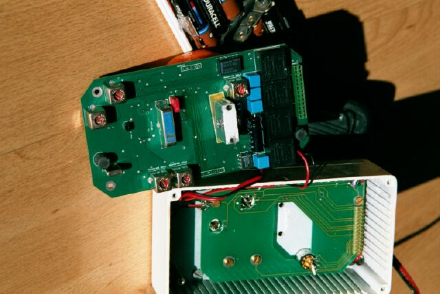
The device can be supplied from batterries providing
between 12 and 15V. This is a view of the inside of the device
showing the main low profile circuit board. All the connections for
the front panel are made via a seperate PCB attached to the front
panel. There is even space in the box for 10 AA batteries (giving
about 2-3 hours of intensive use with Duracell Ultras).
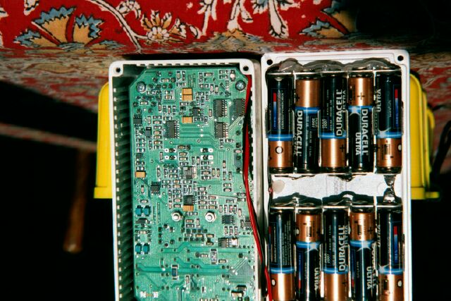
View of the surface mount side of the main board.
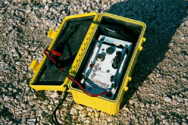
Protection of the device in a waterproof
box.
2 - Construction of the device
The production of a series of about 50 circuit boards is anticipated by mid april 2000. The boards can be assembled in these numbers for about 1850 F per board. There should also be some bare boards for hand assembly in small quantities in the future. The AD607 is however a 20 pin device with a 0.65mm pitch between pins. Hand soldering this device requires a little practice but a well made board should be able to be solderred by a competent technician in an afternoon. Around 1500 F is required to complete and box the device with a good quality handset and good quality front panel components. A few hours are required for the final assembly and trimming of the presets.
2 - Operation :
- Wires are run out in each direction from the device to convenient points at which a good ground contact can be made. A ground connection can be made underground using a length of about 10m of electric fence tape in a pool or mud. On the surface metal stakes (or large metal tent pegs) will work well. The symmetry of the antenna is not important but aim to have a seperation between the grounding points of about 1/6th the distance over which communication is required.
- Once the ground contacts have been made the battery should be connected causing the LED to light red.
- The three position switch should be turned to 1. Blow into the microphone while squeezing the transmit switch. Raise the position of the switch until the orange LED lights.
- Correct adaptation to the ground should now be achieved. With a good grounding connection this will be on position 1, with normal grounding it will be on position 2 but if you have to switch to position 3 then this indicates a poor ground connection or perhaps a broken wire.
- Once the voice connection has been made it may be possible (if the reception is good at the far end) to drop the switch position in order to conserve the batteries.
There should be some co-ordination with the surface team to agree the location and time of such transmissions. It is up to the surface party to be ready. The underground team may well try and transmit well before or after the agreed time. It may be necessary for the surface team to displace themselves if the signal is weak and or if determined by the strata. A loop aerial is sometime useful while moving to find the strongest signal.
Using earthed antenna wires provided they are of
significant length will normally give a much stronger signal than a
loop. It is more important to get a good transmission strength form
the underground to the surface due to the sometimes high levels of
background noise on the surface. Achieving good ground connections is
important for getting the best transmitted signal strength. It is
important that no-one is holding the antenna wires (especially the
ends and the terminals) whilst a transmission is being made, due to
the several hundred volts induced on the output (Position 3 gives the
highest output voltage).
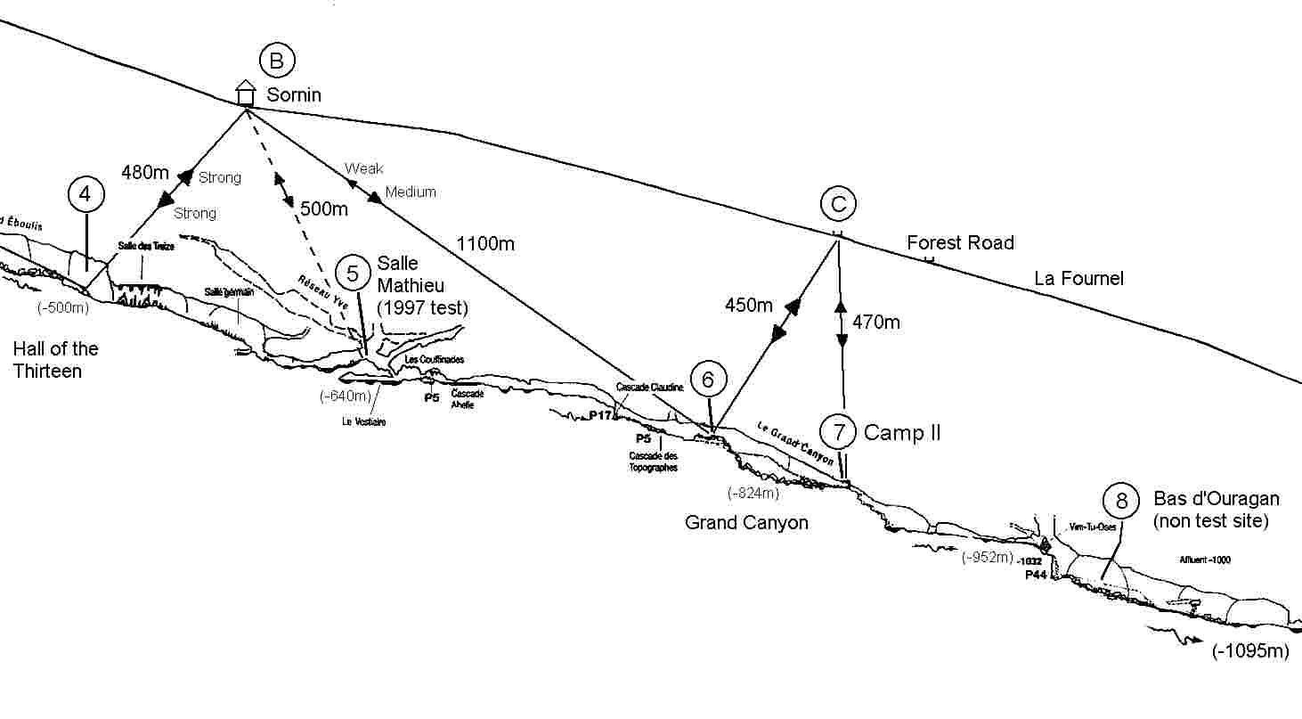
The reception underground is often much better underground than on the surface. This is due to the high level of atmospheric disturbance in the LF band. Lightning strikes produce strong signals in the LF band which will propogate up to a 1000km due to the ground effect. Undergound these parasitic disturbances may be significantly attenuated (unless the cave is quite shallow). These noise sources will vary enormously from one day to the next and form day to night, due to the drastic changes in propogation conditions for these perturbing sources.
The Loran C transmitter also causes considerable
disturbance in the region 80-130kHz. At the 87kHz frequency currently
used in the system Nicola, this means that although over 1km is
sometimes possible, in practice it is best to limit the distance to
500m to ensure reasonable reception is achieved on the surface. This
distance is normally sufficent for even the deepest caves in France
due to the fact the often the surface above the deepest part of the
cave is often well below the level of the entrance. In the case where
large distances are to be attempted then it is often useful to
consider the geology so as to avoid passing through more comnductive
strata. Sometimes finding the outcrop on the surface in shich the
underground party is situated is sometimes beneficial. Once a contact
is made, if the signal is weak it is often worth moving to improve
the signal strength (as indicated above by maximising the received
signal strength with a loop on the surface while the underground team
connect their radio to an automatic beacon).