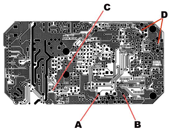
Adjustment of the circuit board.

The board should be made up into its box with all the front panel components. It is recommended that the first test be performed with a power supply set to
12 - 15V with the current limited to 1A. Turn the volume button to minimum.
Power up the set. After a short transient when the current may rise to about 0.5A, the consumed current should fall again to about 60mA. Turn up the volume button - hissing should be heard from the loadspeaker.
Measure with an oscilloscope the trace on pins 1 and pin 7 of U1 - OPA2604 (with respect to 0V). There should be an audio noise waveform (look with a time base of about 1ms/div) with an amplitude of about 40mV pk-pk.
 
The adjustment of the various inductors is very straightforward and should take only about 5 minutes.
First connect an oscilloscope to the point A marked in the diagram below and adjust the Toko coil screw until the signal is maximised (should be a sinusoidal
signal around 500kHz with about 1-2 volts of signal level pk-pk).
Connect the probe to point B and adjust the adjacent Toko coil in the same manner.
Connect two wires each about 5m long to the two aerial terminals and connect each end to an earth connection.
Adjust the surface mount potentiometer at C until the red LED does not light with incoming noise transients (this can be re-adjusted in the future in case it is still too sensitive). The red LED will be the indication of an incoming 87kHz signal.
With the wires still connected, connect a short (about 10cm aerial) to a signal generator about 1m away from the radio aerial wires. Adjust the generator to
give 88kHz sinewave with a level of about 1V. Adjust the radio volume so that the background noise is quite audible and then adjust the generator signal amplitude until the 1kHz tone heard on the radio is just discernible above the background noise.
Now adjust the two Toko coils marked D in the diagram below so that the tone heard is maximised. Repeat the adjustment until no improvement is made.
Place a 2W 600ohm resistor in the aerial terminals. Turn the transformer adaptation switch to the middle position. Activate the microphone switch and
blow into the micro for about 10-20seconds. The orange LED should flash when blowing harder. Measure the voltage across the resistor with an oscilloscope probe (the output is floating so polarity is not important - either side can be grounded). The waveform should be a modulated sinewave with an amplitude of about 150V pk-pk (when blowing into the microphone). Turn the selector switch to position 1 and measure again. There should be about 70V pk-pk. Replace the resistor with a 2k ohm resistor and test on position 3. The output should increase to about 300V pk-pk. When the microphone is activated (press the PTT button), the oscilloscope trace should pulse 2 or 3 times (beeps at the start of the transmission) and again 3 or 4 times when the PTT is released and then drop in amplitude back to zero.
 

View of the surface mount side of the circuit board (the Toko coil adjustments are on the other side!)