Simple LowFER Transmitter
by Lyle Koehler, KØLR
One of the neatest things about 1750 meters is that it's a home-brewer's
paradise. Transmitter circuits can be very simple and inexpensive, you
don't have to worry about hazardous voltages (either DC or RF), and almost
any construction technique will work. An entire transmitter can be built
on a small solderless plug-in protoboard.
The circuit in Figure 1 uses a complementary-pair final that I've had
good success with over the years. Although my present "LEK" transmitter
has a home-brew frequency synthesizer that drives the final, a 74HC4060
oscillator/divider circuit works just as well and is about the simplest
crystal-controlled "exciter" you can build. Transistors with the "A" suffix
seem to work somewhat better in the final than plain 2N2222s and 2N2907s.
The cheap plastic PN2222A and PN2907A transistors from Mouser, Tech America
or other suppliers are fine. I've tried complementary-pair FETs, but their
drive levels are a bit more critical, so I've stuck with bipolar transistors.
When driving low-resistance loads, less than 20 ohms, higher-power transistors
like the NTE129MCP matched pair or an NTE186/NTE187 combination may give
slightly better efficiency. However, the difference will not be noticeable
at the receiving end, and it's comforting to know that if the final gets
zapped by lightning I can replace both of the transistors for under 20
cents. Besides that, using low-power transistors keeps you from cranking
up the power to 5 or 10 watts and spoiling the fun!
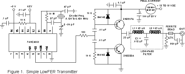 In Figure 1, the crystal oscillator runs at 32 times the desired output
frequency. For operation at 160 to 190 kHz, the crystal frequency must
be in the range of 5.120 to 6.080 MHz. Until this fall (1998) it was advisable
to stay above 176 kHz to avoid competition from the Ground Wave Emergency
Network (GWEN). However, GWEN has been decommissioned and the bottom 15
kHz of the band is now a pretty good place to operate. The 74HC4060 has
outputs at other division ratios which let you use different crystal frequencies.
For example, you can use crystals in the 3-MHz range and the ÷16
output (pin 7) or crystals in the 12-MHz range with the ÷64 output
(pin 4). Higher division ratios are available, but crystals above 20 MHz
are often overtone-type crystals which will not work properly in this circuit.
The trimmer capacitor provides a limited range of adjustment of the oscillator
frequency, and can be replaced with a fixed value of about 27 pF if you
aren't worried about hitting a precise frequency. Pin 9 is the output of
the crystal oscillator section. There should be a signal on this pin whenever
power is applied to the circuit. The outputs of the various divider stages
are only present when the keying line (pin 12, the reset line for the divider
chain) is grounded.
In Figure 1, the crystal oscillator runs at 32 times the desired output
frequency. For operation at 160 to 190 kHz, the crystal frequency must
be in the range of 5.120 to 6.080 MHz. Until this fall (1998) it was advisable
to stay above 176 kHz to avoid competition from the Ground Wave Emergency
Network (GWEN). However, GWEN has been decommissioned and the bottom 15
kHz of the band is now a pretty good place to operate. The 74HC4060 has
outputs at other division ratios which let you use different crystal frequencies.
For example, you can use crystals in the 3-MHz range and the ÷16
output (pin 7) or crystals in the 12-MHz range with the ÷64 output
(pin 4). Higher division ratios are available, but crystals above 20 MHz
are often overtone-type crystals which will not work properly in this circuit.
The trimmer capacitor provides a limited range of adjustment of the oscillator
frequency, and can be replaced with a fixed value of about 27 pF if you
aren't worried about hitting a precise frequency. Pin 9 is the output of
the crystal oscillator section. There should be a signal on this pin whenever
power is applied to the circuit. The outputs of the various divider stages
are only present when the keying line (pin 12, the reset line for the divider
chain) is grounded.
The output of the complementary-pair final is a square wave, which
contains lots of harmonics. However, it may actually be "cleaner" than
other high-efficiency finals. There is theoretically no energy on even
harmonics, and the third harmonic is almost 10 dB down from the fundamental.
A typical LowFER antenna/loading coil combination acts as a narrowband
filter. You can feed the antenna directly with a square wave and the harmonic
levels are likely to be well below the -20 dB level required by the FCC
Part 15 rules without any low-pass filtering. But to keep peace with the
neighbors, I recommend enclosing the transmitter in a metal box and using
at least the ferrite bead with the 560-pF capacitor across the output jack.
Neither the type of ferrite bead nor the value of the capacitor is critical
to the operation of the transmitter; they are just included to eliminate
TV and FM interference. In my "LEK" transmitter, I also use the low-pass
filter shown enclosed within the dotted lines in Figure 1 just to make
sure that the output is clean no matter what kind of antenna is connected.
Values of L1, L2 and C1 shown in Figure 1 are for an antenna impedance
of 50 ohms. L1 and L2 can be made with 60 turns of #26 wire on a T80-3
(grey) toroid form, or 40 turns of #22 wire on a 1.9 inch diameter PVC
pipe. A plastic pill bottle or the cardboard core from a toilet paper roll
are possible substitutes if you don't have any pieces of PVC pipe lying
around. L1 and L2 are separate coils, and should be mounted at right angles
to each other to minimize inductive coupling if you use the 1.9 inch coil
forms. Toroid cores are more or less self-shielding, so there isn't much
coupling between them unless they are very close together. Capacitor C1
should have a rating of at least 100 volts. It may be hard to find a .018
uF capacitor, but .015 uF and 2700 pF connected in parallel will be close
enough. In fact, you may want to experiment with different capacitance
values to get the maximum output across a 50-ohm load resistor with the
actual values of inductance in your circuit.
A good LowFER antenna will not necessarily present a 50 ohm load to
the transmitter. Actually it should have an impedance of less than 20 ohms
at resonance if the loading coil and ground losses are low. You could scale
the component values in the filter to "match" the impedance, but the antenna
impedance will vary depending on whether the ground is frozen, leaves are
on nearby trees, etc. A single external shunt reactance at the base of
the antenna (in other words, across the transmitter's output connector)
can be used to bring the impedance up to 50 ohms. This technique is often
used on mobile antennas and is described in the ARRL Antenna Book. When
you insert the shunt reactance, the value of the loading coil inductance
must be adjusted slightly to bring the antenna system back to resonance.
Either a shunt capacitor or inductor will raise the feed-point impedance.
A shunt inductor has the advantage that it provides a DC path to ground
to drain off static charges from snow, dust, or lightning. However, a capacitor
helps reduce harmonic radiation, and it's easier to get good quality capacitors
in small sizes. I use a shunt inductor in summer because it provides better
lightning immunity, and a shunt capacitor in winter when I'm trying to
squeeze out every last milliwatt. The value of shunt reactance is not very
critical. A 30 uH inductor or 0.02 uF capacitor is about right if the antenna
impedance is between 15 and 20 ohms.
My LF transmitter also uses a power limiting circuit so that the DC
power input can never exceed the FCC limit. The circuit consists simply
of a power supply with a DC voltage, V, that is twice as high as the final
amplifier needs, and a series resistor equal to V(squared)/2. My LF final
gives the best efficiency with about 13 volts at 77 mA, so I'm using a
26-volt supply and a 169-ohm series resistor. This is done more for convenience
rather than for fear that the transmitter might be a few milliwatts above
the FCC limit. It makes it possible to tune for maximum antenna current
(or field strength) without worrying about the DC power input. The output
also stays more constant when the antenna is detuned by rain or ice than
it would with a "stiff" power supply. If you don't know in advance what
voltage gives the best efficiency, you can start with a best guess, measure
the voltage the final has "chosen" after the antenna current is maximized,
and use this value to modify the supply circuit. One or two iterations
are adequate if the first guess was anywhere near the target.
The best LowFER antennas are verticals with big top hats to improve
the current distribution and minimize the amount of loading coil inductance
required. If the antenna is not properly tuned, your range is going to
be measured in feet rather than in miles! The loading coil can be inserted
anywhere in the vertical portion of the antenna if a large top hat is used.
Best efficiency will usually be obtained when the loading coil is near
the middle of the vertical section. However, this may present construction
problems, and the required inductance will be greater than it would be
if the coil is near the base. Forget about using a tuner or some wimpy
little loading coil like the ones used on HF mobile antennas. It typically
takes 2500 uH or more for a base-loaded antenna with a big top hat, and
about 5,000 uH for a simple base-loaded 15-meter vertical with a 1.5" mast.
I've seen published suggestions for LowFER loading coil designs that are
totally out of the ballpark in Q, inductance or both. Your best bet is
to design your own. To get reasonable Q in a loading coil for these frequencies,
use #20 or larger wire, with a winding pitch (ratio of center-to-center
spacing to the wire diameter) of about 2, and a diameter-to-length ratio
between 1:1 and 2.5:1. Litz wire is great if you can find it in large enough
sizes. Avoid lossy coil form materials like PVC and Nylon if you want high-Q
coils. Air is the best insulator, but styrofoam comes close. Other suitable
materials are Teflon, polyethylene and polystyrene. Included in Reg Edwards'
excellent collection of free software on his G4FGQ
web site are programs to design transmitting and receiving loops, coils
and vertical antennas. His VERTLOAD program will calculate all you need
to know about vertical antennas (without top hats), and SOLENOID provides
accurate calculations of coil inductance and Q. In Reg's programs, wire
diameters and coil dimensions are given in millimeters. I've written a
program called AWG-COIL that will convert AWG
wire gauges to millimeters, and will also calculate the dimensions of a
loading coil if you input the desired inductance, wire size and winding
pitch.
For more information on LowFER antennas, my LOWDOWN article on "Getting
the Most out of LowFER Transmitting Antennas" is available on-line via
the File Libraries section of the
Longwave Home Page.