Author's note: This article was started a couple of years ago but never published because it involved minor surgery on a computer, and seemed like a cumbersome way of generating a LowFER signal. However, now that old PCs are throw-away items, it's kind of fun to experiment with new uses for them. Even if you never put it on the air, the PC-based synthesizer is an interesting project to build and test on a plug-in protoboard.
Note: A new version of PCTX.EXE was created on 11/27/00. This version contains a fix that allows QRSS or very slow CW operation. The old PCTX file will probably hang up if the CW speed is set to less than 1 WPM when running on a fast computer.
In this day and age, when most car radios and even pocket-sized AM/FM radios have digital frequency synthesizers, it would seem that building a synthesized LowFER transmitter should be a piece of cake. It doesn't always work out that way. At least, not for me. A typical phase-locked loop (PLL) synthesizer consists of a voltage-controlled oscillator (VCO), a programmable divide by N counter, a stable frequency reference and a phase comparator. Usually the frequency reference comes from a crystal-controlled oscillator followed by another divider. When the loop is in lock, the frequency of the VCO is N times the reference frequency. It's simple enough in principle. However, if you want an output on the LF band that is programmable in small frequency steps, less than 100 Hz, the reference frequency must be very low and the division ratio N becomes very high. It becomes difficult to design a stable PLL synthesizer that doesn't have its output modulated by the reference frequency. The solution often involves compound loops and more circuitry than the average experimenter wants to deal with. Here's where the PC comes in. It has a crystal-controlled oscillator, a programmable frequency divider, a keyboard for control and a monitor for display. If you want to use them, it also has regulated 5 volt and 12 volt DC power supplies with plenty of current capability for a LowFER transmitter. As an added bonus, the PC can serve as a programmable beacon identifier and message generator for the synthesized transmitter.
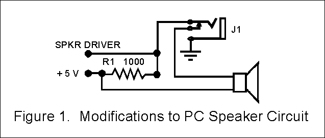
Any working IBM-compatible PC with a single floppy drive should be adequate. It doesn't have to be fancy or fast. A parallel output (printer) port is necessary, though, if you want the "Cadillac" version. The synthesizer circuits described in this article use the PC speaker output, called by a BASIC language "SOUND" statement, to provide a programmable reference frequency. You will need to open the computer and add a resistor and output jack to the PC's speaker circuit. Fortunately this is a fairly painless operation and the speaker is one of the few components in the computer that can be identified without an advanced degree in computer science. In my PC the speaker is connected between the + 5 volt supply and a driver circuit. I expect that this is fairly typical. Figure 1 shows one way to modify the PC, using a closed-circuit jack to disconnect the speaker when the synthesizer is plugged in. You need to identify which wire going to the speaker is from the + 5 volt supply and which is from the driver. The best way to do this is to issue a BASIC SOUND statement such as SOUND 1000, 1000 (or run one of the programs identified later in this article) and check both sides of the speaker with a scope or a low-voltage AC multimeter. Another audio signal tracing trick is to use a .1 uF capacitor in series with a pair of headphones. I'll leave it up to the reader to figure out where to mount the output jack, since there are so many variations in PC case designs.

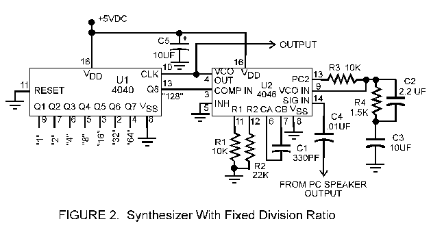
Figures 2 and 3 show two different implementations of a PC-based synthesizer. The circuit in Figure 2 requires only two integrated circuits and has a fixed division ratio N = 128. I've found out partly by analysis and partly by trial-and-error arithmetic that there is no advantage in using division ratios less than 128 or greater than 255. With a fixed division ratio of 128, there are 69 available output frequencies in the usable part of the LowFER band (between 175 and 190 kHz).


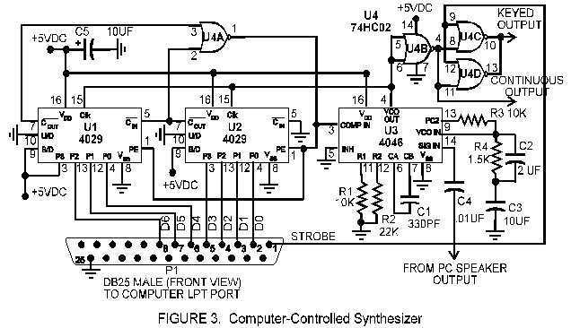
The internal workings of the PC determine the "channel" spacing at the synthesizer output. A BASIC "SOUND" statement can only specify speaker frequencies in integer form, that is, in 1-Hz steps. Speaker frequency steps therefore can not be less than 1 Hz apart. The steps will not be exactly at integer frequencies because the speaker output can only be the result of an integer division of an internal PC clock frequency (about 1.193 MHz). With a fixed division ratio N, the minimum frequency step size at the synthesizer output is N Hz. However, by using different divisors in the external hardware along with the many possible sound frequencies from the computer it is possible to generate hundreds of frequencies in the LowFER band. If your computer has a parallel line printer (LPT) port, this port can be used with the circuit in Figure 3 to set the optimum division ratio automatically. The computer-controlled synthesizer circuit also provides a keyed output when the PCTX program (described below) is used.
By the way, if you don't want to use a PC, you can modify the circuit to make a conventional PLL synthesizer. Just substitute DIP switches and pullup (or pulldown) resistors for the LPT data lines in Figure 3, and supply a stable reference frequency of 745 Hz or higher in place of the speaker output. For example, with an 800-Hz reference, setting the DIP switch for a division ratio of 225 would give an output at 180.000 kHz, a divisor of 226 would give 180.800 kHz, etc. The "scientific" option for the Windows Calculator accessory will do number-base conversions so that you can translate decimal numbers into the binary numbers needed to set the DIP switches.
High-speed CMOS parts such as the 74HC series can be substituted for 4000-series parts in either the circuit of Figure 2 or Figure 3, except that the PLL chip must be a CD4046 (not a 74HC4046). A 74HC4046 will not work with the component values shown. National Semiconductor 4046 chips seem to have less phase noise than those of other manufacturers, and are recommended if you want the cleanest possible note. Resistors R1 and R2 and capacitor C1 in Figures 2 and 3 should have a tolerance of 5 per cent or less. If the synthesizer won't tune the entire LowFER band, increasing C1 will lower the frequency and decreasing C1 will raise it. The frequency accuracy of the output is only as good as the computer's clock oscillator. With the circuit in Figure 3, you can set the output to 166,666.7 kHz and adjust the computer's clock oscillator trimmer capacitor (if it has one) to zero beat a harmonic of the output frequency with WWV.
I've provided two control programs for use with the PC-based synthesizer. Both programs have been combined in the file PC-SYN.ZIP (approximately 63 kBytes). After downloading PC-SYN.ZIP, place it in its own directory before unzipping it. When unzipped, you should have two executable files (PCSYN.EXE and PCTX.EXE). There is also a file called PCTX.CFG, which is required by PCTX.EXE and must reside in the same directory.
PCSYN.EXE will prompt you for the desired output frequency, search for the best solutions for the SOUND frequency and division ratio N (if the programmable division ratio option is specified), generate the speaker output, and set the dividers via the LPT1 port. The program will also display the actual frequency that will be generated. With the programmable division ratio, you can usually get well within 10 Hz of any specified frequency in the LowFER band. An option when you start the program lets you choose a fixed division ratio if your computer doesn't have an LPT port or if you just prefer to use the simpler circuit. There is another start-up option that can be used to find how close you can get to a desired frequency without generating a speaker tone (which can be annoying if you haven't already modified the PC and plugged in your external circuit). A little "experimenting" with the program will tell whether or not the programmable-divider option is necessary to get close enough to a desired frequency.
PCTX.EXE combines the features of PCSYN.EXE with the beacon identifier/message generator program. See "Using a PC as a Beacon Message Generator" and the documentation included in BCN.ZIP for a description of the features. All of the options of BCN.EXE are available in PCSYN.EXE, except for the speaker code output and the choice of COM or LPT ports for the keying output. Note: PCTX.EXE does not have the option of checking available frequencies with the speaker tone disabled.
Either the keyed or continuous output should be able to drive the complementary-pair final in the Simple LowFER Transmitter. However, when the 74HC02 is driving a low-impedance load it may cause fluctuations in the supply voltage. Because PLL circuits are highly sensitive to supply-voltage variations, it is advisable to use a separate 5-volt regulator for the 4046 to reduce "chirp" on the signal.
Here is a step-by step example of how an actual output frequency is synthesized, assuming that you have connected the PLL circuit of Figure 2 to the PC speaker output and set the hardware divider to a fixed ratio N = 128. First, you tell the computer that you want an output frequency of 188,400 Hz. This requires an output tone on the speaker line of 188,400/128 = 1471.88 Hz. A BASIC statement "SOUND 1471.88, 20000" would tell the computer to put out a 1471.88-Hz tone on the speaker for 20000 clock ticks (there are 18.2 clock ticks per second). Although the BASIC language variations I've tried will not give an error message if a fractional frequency is entered, the computer ignores all but the integer part and treats the number in this example as 1471.0. Fine, we'll settle for that. But the computer can only output integer division ratios from an internal clock frequency of 1,193,181.667 Hz (one-fourth of the original PC's CPU clock rate). So the computer calculates the clock frequency divided by 1471, which comes out to 811.14, and uses the integer part (811) as the internal divisor. The resulting sound frequency is actually 1471.24 Hz, and the output of the PLL synthesizer is this frequency multiplied by 128 or 188,318.7 Hz. The next available channel is obtained with a SOUND statement frequency of 1472, which results in an actual speaker output frequency of 1473.06 Hz, and a synthesizer output of 188,552.2 Hz.
When using the circuit of Figure 3 with the programmable divider, the computer is able to adjust both the division ratio and the speaker output frequency. In the example just given, we were not able to get within 50 Hz of the desired frequency of 188,400 Hz when we used a fixed division ratio of 128. With a programmable division ratio, the nearest available frequency is 188,397.3 Hz. Pretty darned close!
A note on the duration part of the SOUND statement: The BASIC language reference manual says that the duration can be any integer from zero to 65,535 clock ticks. With the duration specified as 20000 clock ticks, the sound should continue for about 18 minutes. However, the computers I've tried automatically shut off the speaker after less than two minutes, possibly to avoid overheating the speaker driver chip. A continuous output requires a loop that issues a new SOUND statement before the first one expires. This may result in a discontinuity in the speaker tone that can cause the PLL frequency to wobble slightly from time to time. In the program PCTX.EXE with the built-in keyer feature, the SOUND statements are issued during key-up periods so the PLL has time to settle before the next key-down interval.