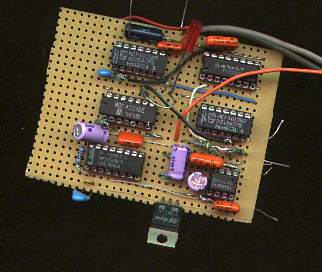
This is one of the many driver boards I have made. RF layout techniques are not necessary but do decouple each chip individually to reduce spurious triggering.
The the driver chip is at the bottom right which connects to the FET gates via 6.8 Ohm resistors. The coax cables connect to the VFO and to the key.
You can see the keying transistor Q6 at the bottom. Note the short leads on the decoupling Cs around the driver chip.