 |
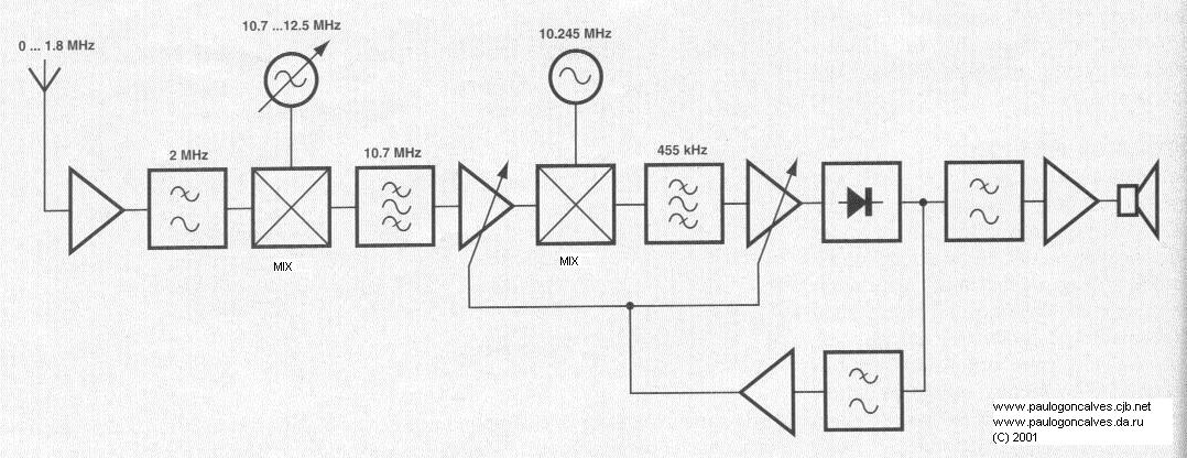
AM Receiver - From 0 Hz up to 1.8 Mhz
|
A short introduction
This radio receiver can tune stations since 0 Hz up to 1,8 Mhz,
quite uncommon situation because any normal AM receiver is only
able to receive to long wave radio stations (150 to 433 Khz) and
medium waves (520 to 1612 Khz).
Will this widening of the reception band be useful to anyone ? For those who live near the maritime coast, will be able to appreciate the reception in the band of 1600 the 1800 Khz where the naval stations work and get useful information, mainly the weather forecast.
The activity in such low bands (VLF 9 to 148.5 Khz) includes the comms with submarines, RTTY stations, the famous time clock signs of great accuracy, such as station DCF77 (77.5 Khz) and beautiful Earth's natural sounds like sferics, tweeks and wishtlers. (For more information about these sounds check The Natural Radio Home Page, in this site).

| Frequency in Khz | Callsign | Service |
| 18.3 | UNID | RTTY |
| 53.6 | RTO | Moscow Meteo |
| 60.0 | MSF | Rugby TS - Time Clock |
| 75.0 | HBG | Nyon TS - Time Clock |
| 77.5 | DCF77 | Mainflingen TS - Time Clock |
| 82.8 | MKL | Royal Air Force- Edinburgh |
| 111.3 | SOA211 | Varsovia - Meteo |
| 117.4 | DCF37 | Offenbach Meteo |
| 129.1 | DCF49 | BMPT Bonn |
| 139.0 | TBA | TN Ankara |
| 147.3 | DDH47 | Hamburg Meteo |
 |
| R | C | L | Semicondutors | Misc. |
| R1=1MOhm | C1/C23/C35 = 10 pF | L1=3.9uH | D1=MV1401 (Motorola) | LS1= Speaker 8 Ohm -1W |
| R2/R3=100 KOhm | C2/C3/C5/C11/C17/C18/C21 /C24/C26/C27/C33/C36/C44/= 100 nF |
L2/L3= 100 mH | D2=1N4001 | X1- Ceramic Filter10.7 Mhz (10M7A) |
| R4=1 KOhm | C4/C9/C10/C28/C29=220 nF | L4=1.5 uH | D3= LED | X2= Ceramic Filter SFR455H |
| R5=820 Ohm | C6/C8=56 pF | L5=680 uH | T1=BF961 | X3=Quartz Cristal 10.245 Mhz |
| R6=1.8 KOhm | C7=180 pF | L6=82uH | T2=BF494 | P1=Multiple Turn 50 KOhm |
| R7=150KOhm | C12=22pF | L7=12 uH | T3=BC550C | |
| R8=3.9 KOhm | C13=33pF | T4=J310 | ||
| R9=1.2 KOhm | C14/C16/C43=100pF | IC1=SA612AN (Philips) | ||
| R10=2.7 KOhm | C15 = Adjust. 40 pF | IC2=TDA1572 | ||
| R11=330 KOhm | C19/C20/C41=10 nF | IC3=LM386N | ||
| R12=100 Ohm | C22=120 pF | IC4=78L09 | ||
| R13=22Ohm | C25=47 uF-16 V | IC5=78L06 | ||
| R14=1 Ohm | C30=2.2uF - 16 V | |||
| R16=10 KOhm | C31/C34= 22uF - 16 V | |||
| R17=820 KOhm | C32=3.3 nF | |||
| R18/R20=2.2 KOhm | C37/C38=220 uF - 16 V | |||
| R19=220KOhm | C39/C40=10uF - 63 V | |||
| C42=39pF |

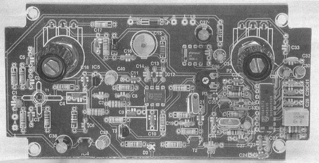
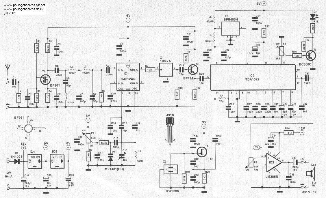
The calibration is made by the adjustment of C4 to define the local oscillator's frequency gamma. To make this adjustment, temporarily short circuit between the input of the antenna and the ground, binding a wire from the point A and ground. After that, turn P1 in the anti-clockwise direction. Slowly turn C15 from the central position until hearing a sign. You can use also a frequency meter between PINs 6 and 7 of IC1 and adjust C15 until read 10.7 Mhz.
The disadvantage of this way is that the load of the circuit by the measure device, can cause a certain frequency oscillation. To prevent this problem, connect a resistor with 10 KOhm between pin 1 and ground. In this situation, we will have the same frequency generated by the local oscillator and could easily be measured with one frequency meter or oscilloscope.
Finally remove the 10 KOhm resistor and the short circuit in A and connect a vertical antenna in that point. The antenna can be build by an isolated wire. The ideal wire size is between 10 and 20 centimeters. Bigger antennas will magnify the reception of atmospheric noise.
10-06-2001