Discussion of Antennas and Related Topics from the LF Reflector
Active Antennas
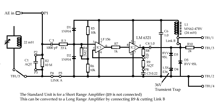
I have been asked by quite a few LF operators for the circuit diagram of the Decca active antenna amplifier that was sent to me by Robin Greenwood, G3LBA. He says: " I have a Decca Preamp mounted on my Garden shed (Height 3.5 M.) and I have a 0.75M. steel whip on it. The shed is well away from any other buildings and the antenna seems to be excellent although I have little else to compare it with. I have The LH0002 in obsolete but an LM6321in OK in the circuit. I have laid out a PCB to which I added a single parallel 136 kHz. tuned circuit across the input. The layout is available as a HPGL file for anyone interested." Robin says that he powers the amplifier with 20Vdc via the coaxial feed.
I would like to thank John, G4CNN, for redrawing the diagram.

A few years ago I made an active broadband loop antenna for HF for 'official' purposes. This consisted of a 300mm diameter loop of 3mm copper wire into a common base amplifier made from a 2N5109 transistor operated with 50mA collector current. The input impedance was about 0.5 ohm with a collector load of 50 ohms, and no negative feedback was used for a reasonably flat response across the higher part of the HF spectrum. Performing down to 2MHz at least, although sensitivity was falling off there it still gave more than enough signal to hear background noise. This loop vastly outperformed the commercial Procomm active whips we were using at that time as HF collection antennas and even performed better than a homebrew active E Field plus high impedance amp design, based on one in VHF communications some ten years ago (which itself easily outperformed the Procomm). Furthermore, it was immune to the huge locally generated interference levels on this hill overlooking the industrial areas of north Portsmouth! The only reason we didn't go ahead with a whole array of these and instead stayed with E Field whips was that the loops were directional against vertically polarized signals. Which was something definitely not wanted at the time. However its omnidirectional properties for H-Pol signals when mounted horizontally made it a good antenna for low angle skywave detection. Such an amplifier with a 1m loop consisting of a few turns of wire would make an excellent LF antenna and could cope with strong signals up to nearly 1-Watt input before overloading. Purely for LF work, an op-amp with feedback could be used and perhaps an even lower input impedance can be achieved.
Andy G4JNT
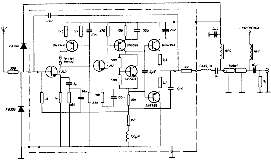
It has been mentioned several times that the input stage of an active receiving antenna is easily damaged by lightning in the vicinity due to the very high input impedance of the amplifier. Several years ago Dr. (now professor) E.H. Nordholt of the Technical University Delft in The Netherlands developed an alternative design for an active antenna that does not suffer from this problem. The circuit is shown below:

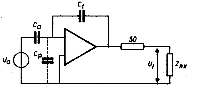
Instead of making the input impedance very high it has been made very low instead by means of negative feedback.
 As a result the E-field probe, a piece of
copper tube of 50cm long and 3cm diameter, now feeds a current into the FET at
the input. Because of the probe's capacitive impedance the current increases
with frequency at 6dB/octave. This is compensated by the negative feedback. The
active antenna has a frequency response that is flat from 5kHz to over 30MHz. It
stays linear in field strengths up to 10V/m. Great attention has also been given
to proper noise behaviour ("noisemanship"). The input is protected by
diodes against high voltages. Because signal voltages at the input are very
small due to the low input impedance little signal current flows into the diodes
and they do not impair the favourable characteristic of the active antenna. In a
test the antenna was not damaged by sparks jumping to the probe from a car
ignition coil.
Particulars can be found in: E.H. Nordholt, D. van Willigen: "A new approach to active antenna design", IEEE Transactions on Ant. and Prop., vol. AP-28, no. 6, November 1980.
Dick PA0SE
Ah -Ha it all makes sense now, I couldn't see how a 'low' input impedance (read zero) could possibly work on an E Field whip - it would theoretically give zero output for zero ohms input Z at low frequencies. Since the real component of its source Z - its radiation resistance - would tend to zero there couldn't be any current input. After studying the circuit diagram now, calling it a 'low' input impedance amplifier is a misnomer. It is actually designed to have a purely capacitive input impedance and no resistive term at all - hence the need for a 1G bias resistor. As such, since the antenna is (near enough) a pure capacitor it will be forced to have a flat frequency response overall. For LF only, a good quality FET input opamp would probably do a similar job although obviously without quite such good signal handling. The output stage looks strong. In the absence of easily available RF PNP transistors for jobs like this, I usually resort to an emitter follower using a 2N5109 or 2N4427 (1W VHF transmitter devices) running at 50 - 100mA IC and operated with a decent heatsink.
Andy G4JNT
I was very glad to see the additional explanatory material. In first looking at only the schematic last night, I was not clear on how the low impedance concept might materialize. At DC, it's not that low. But at RF, the input of the amplifier is indeed a current summing junction and therefore nearly zero impedance, just as if the feedback network were implemented with resistors and being used at audio frequencies or DC instead.
It seems fair to say this design, where the amplifier is a more integral (no pun intended) part of the antenna itself, probably fits the meaning of the term "active antenna" better than the usual voltage follower does. However, because of the high value resistor and miniscule feedback capacitor, I suspect quite a bit of care in construction is advisable. One might not achieve satisfactory results slapping it together "dead bug" style in half an hour on a Saturday afternoon.
Thanks again for bringing such an interesting design to everyone's attention.
73, John
This is most interesting. Some of us have active antennas from the Decca transmitter sites used for the monitor receivers. G3GRO has used one of these active antennas with a whip antenna, which when raised well above other electromagnetic obstructions (as suggested by G3JKV) gives results at least as good as with a resonant transmitting antenna. My own Decca active antenna located on the side of the house only 7m high does not perform that well. I have received an active antenna, for testing in the EU environment, from Frank Gentges, K0BRA, with e-mail advice to mount the antenna as high as possible. However, the Decca active antennas did not use whip antennas, instead they used copper drums about .5m in diameter and .5m long, mounted only 1.5m above the ground (three of them located only 2m apart). The Decca active antennas appear to have a couple of opamps with a resistor on a link, which can be changed to alter the gain (I do not have a circuit). Could these be a Prof. Nordholt's design? Does this design need to be mounted high above electromagnetic obstructions to perform well as with the conventional active antenna with a whip?
Peter, G3LDO