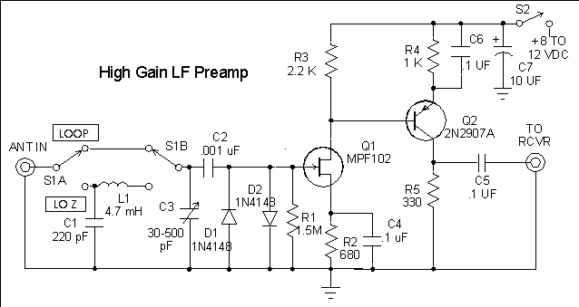
The circuit shown in the diagram below may be used with either parallel-tuned loops or with coax-fed wire antennas. With switch S1 in the "LOOP" position, the frequency range of the preamp is determined by the inductance of the loop and the capacitance range of variable capacitor C3. The diagram shows a range of 30-500 pF for C3. At one time, Mouser Electronics sold a compact 2-gang capacitor that was ideal for this circuit, but unfortunately they have discontinued the part. A single or dual 365-pF variable would be a good substitute. I recommend Reg Edward's RJELOOP3 software, available on the G4FGQ web page, for designing a loop that will work on the desired frequency range with whatever capacitor you have available. Although the preamp was designed for use on LF, it will deliver good performance well into the HF range with the proper loop antenna. It is important to keep the lead lengths short when using the "LOOP" position. For example, if the loop is connected to the preamp through 3 feet of 50-ohm coax, this puts a fixed capacitance of about 90 pF across the loop and will limit the upper end of the tuning range. Any reasonable length of almost any coax may be used between the preamp and the receiver.

The "LO Z" or low-impedance position of S1 is used for coax-fed wire antennas. There is enough gain for use with fairly short whips such as the 5/8-wave 2-meter whip that I often use for mobile LF reception. When used with large antennas like an 80-meter or 160-meter dipole, it may be necessary to attenuate the input signal to prevent overloading. A 0.02 uF or larger capacitor connected across the input terminals will help to reduce overloading from strong local broadcast stations. The recommended part for L1 is a Mouser Electronics 434-02-472J. Different values of L1 may be substituted for use on frequencies other than LF.
Diodes D1 and D2 are simply clamping diodes to protect the gate of the
FET from high voltages that might appear on the antenna. They can be left
out of the circuit if the preamp is to be used only with small loops, but
they don't impair the performance and constitute a cheap "insurance policy".
That is, if the diodes clamp the voltage before the FET blows out.
It helps to mount the antenna some distance from the shack, to get
it away from noise sources like power supplies, computers, and the digital
display in the receiver itself. When used with a parallel-tuned loop, which
is how I do 99 per cent of my longwave listening, the preamp has to be
located close to the loop and some form of remote tuning control is necessary.
Those who are not as mechanically challenged as I am might find ways to
do it with motor-driven air-variable capacitors. An easier solution is
to use voltage-variable capacitance diodes (often referred to as "varicaps"
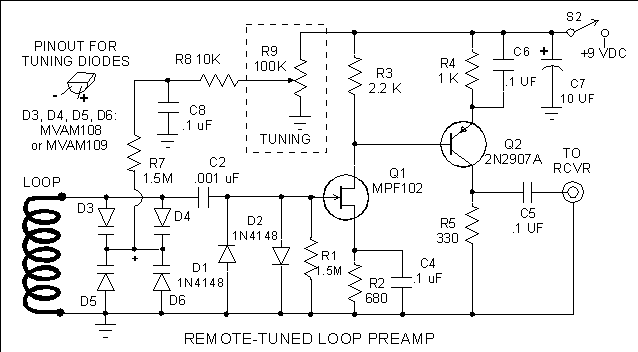
or "varactors") in place of capacitor C3. In the diagram below, C3 has
been replaced by two pairs of MVAM109 or MVAM108 diodes, which will give
a capacitance range of about 40 to 500 pF. A loop with an inductance of
2 millihenries should tune from about 160 to 500 kHz. The tuning control
potentiometer R9 can be in the shack, with a two-conductor shielded cable
carrying the power and tuning voltage to the remote preamp. A separate
coax is used to carry the signal from the preamp to the receiver. My "universal
preamp" article shows how to run power, signal and tuning voltages through
a single coaxial cable. However, it's often easier just to run separate
wires. It is not necessary to use an extremely well regulated power supply,
although the maximum voltage applied to the tuning diodes should not be
much higher than 9 volts (only 8 volts is required to get the full tuning
range with the MVAM108). The + side of the diodes, as indicated in the
sketch showing the pinouts, goes to the common connection point of the
diodes, where the tuning voltage is applied.

A note about tuning diodes: Most of them have a maximum capacitance of less than 100 pF, and need a wide voltage swing to go from the maximum capacitance condition (at zero bias) to minimum capacitance. However, there is a series of "hyper-abrupt junction diodes" that were designed for use in electronically-tuned AM radios. The Motorola MVAM109 will tune from about 500 pF with 1 volt of reverse bias to about 40 pF with 9 volts reverse bias. Since the resonant frequency of the loop/capacitor combination is proportional to 1/C, a capacitance range of 10 to 1 will provide a tuning range of about 3 to 1 in frequency (limited at the high-frequency end by the internal parallel capacitance of the loop or inductor L1 in the preamp circuit). The MVAM108 has about the same capacitance change as the MVAM109, and requires a bias voltage range of only 1 to 8 volts. Not all of the parts suppliers that cater to experimenters carry tuning diodes, but Dan's Small Parts has them in his on-line catalog. Tuning diodes are also available from DC Electronics (1-800-467-7736) and Tech America (1-800-877-0072).