LF Receive Systems
Date 22nd/03/01
Most of the long-term LF experimenters perfected their receiver systems when CW was used for almost all communications. They learned what a good receiving system sounded like. Now, quite a few stations are using computer FFT displays to read signals. These displays can often make an inferior receiving system look good and I have seen some very noisy FFT pictures, which is what prompted me to construct this page. The following notes have been extracted from the LF Experimenter's book and are intended to help newcomers improve their receiver systems. Computer FFT displays are included to show how signals are received here and that weak signals can be received in the presence of very strong ones. Most of the images use the signal from VE1ZZ to illustrate weak signal reception; to my knowledge this signal has never been heard.
Optimum Sensitivity
The complete receive system; i.e. the receiver and antenna must provide enough sensitivity to receive the very weak amateur signals on these bands. Generally, the signals will be much weaker than the other signals such as broadcast stations, beacons, data transmissions and time signals. In addition some amateur transmissions are now running 1w erp and these, plus the commercial stations may be very strong indeed. The ability to receive local high power amateur stations or non-amateur signals well does NOT in itself indicate adequate sensitivity. Even during the daytime, on clear frequencies loud static crashes should be audible which affect the receiver AGC and frequently cause the S-meter to 'kick' - similar to listening to 160m on a humid summer evening. If these crashes are not plainly audible, the receive system is not sensitive enough and steps should be taken to improve the antenna and/or overall receiver gain. An optimum sensitivity must to be achieved however, as too much front-end gain can be disastrous, causing very strong non-amateur signals to overload the receiver with resultant cross modulation/inter-modulation problems.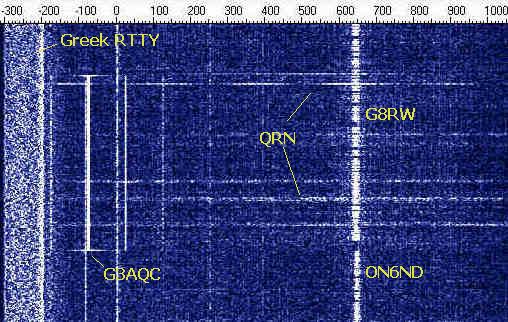 The image on the right shows a section of
the band from 135.7 (-300) to 137.2kHz. (0=136.0kHz) The broad band of noise on
the right is caused by a Greek RTTY station. G3AQC (located only a few miles
from me) is transmitting transatlantic test signals. Further up the band G8RW is
in CW QSO with ON6ND. The horizontal lines are caused by QRN.
The image on the right shows a section of
the band from 135.7 (-300) to 137.2kHz. (0=136.0kHz) The broad band of noise on
the right is caused by a Greek RTTY station. G3AQC (located only a few miles
from me) is transmitting transatlantic test signals. Further up the band G8RW is
in CW QSO with ON6ND. The horizontal lines are caused by QRN.
This shows that, provided the gain distribution of the receive system is optimized, weak signals can be received in the presence of very strong signals.
Maximum Signal to Noise Ratio
At these frequencies, electrical noise sources, both in the shack and close to the antenna, can totally swamp a wanted signal. Typical noise sources are computers, televisions, switching PSUs, fluorescent and 'long-life' lighting, dimmer switches, multiplexed displays (e.g. the one in the rig!), alarms etc. - all the things you are likely to have around the home. The obvious precautions to be taken here are; minimizing the number of possible interference sources left running whilst listening and siting the antenna as far away from noise sources as possibleToo high receiver sensitivity, poor receiver gain distribution and/or receiver non-linearity can have disastrous results at these frequencies, where very strong adjacent signals and nearby broadcast stations are almost certain to cause overload, cross-modulation and intermodulation products in a poorly designed receiver. (Remember that the Long Wave starts less than 15kHz above the 136kHz band!) These problems cause effects such as high general background noise, broadcast modulation audible on other signals, 'phantom' data signals and signals 'keyed' by time pulses - all very common problems in poor LF receivers.
Except when using a very narrow-band, low-gain loop antenna, it is best to avoid front-end preamplifiers. Any noise generated by the preamplifier itself will be amplified by the rest of the receive system, but far more important, the preamplifier or following stages will almost certainly be overloaded by strong unwanted signals received on a good external antenna, even when filtering is used. The best strategy, whether using a converter or general coverage receiver, is to reduce or even omit any gain until after the first mixer and concentrate on good hi-Q tuned circuits directly following the antenna to give maximum attenuation of out-of-band signals. Any lack in overall gain can then be made up in later stages where these problems are less troublesome.
High receiver local oscillator noise can cause problems, where there are often very strong in-band data signals present. The most obvious result of this is the inability to hear weak signals close to these strong signals, due to oscillator noise sidebands. The use of well-designed crystal oscillators and DDS techniques is effective ways to minimize oscillator noise.
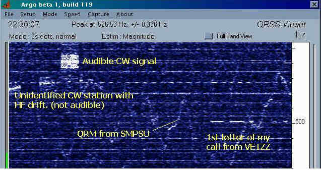
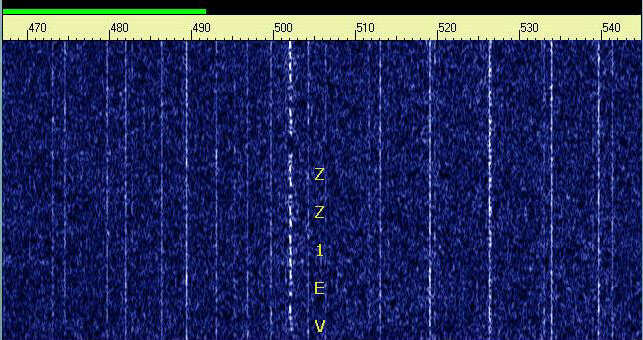
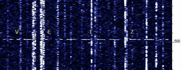
This above image was captured during my transatlantic QSO with VE1ZZ (VE1ZJ) on 13/2/21 (2220UTC) while waiting for a reply to my transmission. There are two sources of QRM. The first are spurious sidebands from the Loran station at Lessay, which are the multiple (often dashed) lines that fill the screen. The second is a squiggly line caused by local electrical interference. Nevertheless, this does not detract from VE1ZZ's readability. More of the signal, giving my report, is shown below.
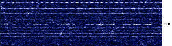
Below: My first sighting of VE1ZZ. Generally, there are very few signals on the band at night. On the night of the 21/12/00 the QRN level was low and the LF conditions good. I was looking for VE1ZZ but unsure of his exact frequency; hence the Spectran setting were far from ideal. Having acquired the image I was loath to touch anything! Fortunately, the signals were clear of Loran lines.
When the QRN level is high the Loran lines disappear. I don't know why this is because weak signals can still be detected as seen in the picture below. Compare this image with the conditions that existed on the night of the QSO. The receiver and Argo AGCs were switched off otherwise the QRN punches a blank space into the picture.
A discussion on receiver systems would not be complete without mentioning the antenna.
Frame-Loops
The frame-loop is often the first type of receive antenna tried on LF. It is small, fairly simple to construct and can be used in the shack, however they are susceptible to noise generated by the computer. They are best sited as far from the shack and house as possible; a garden shed is a good place to locate it). The have useful directional properties, which can be compromised if used in the vicinity of a resonant wire antenna on the same frequency.Short Active Antennas. Most of the work done on these antennas was carried out in the USA. These antennas can give a good account of themselves and they are discussed in A_antenna
Outdoor Wire Antennas There is a consensus of opinion that large outdoor receive antennas on LF are unnecessary as reception is ultimately limited by band noise, not signal strength. Whilst this may be the case for reasonably strong signals, some amateur signals are so weak that a good antenna is required to receive them at all. A large, quiet, outdoor antenna is required when looking for the weakest signals, however the dimensions are not critical. The aim should be to get as much wire in the air, in the clear and as far away from noise sources as possible. Obviously this will be limited by what space is available at each individual location. It is very important that the antenna is resonated with a high-Q series-tuned circuit, although matching the antenna to the receiver input is not critical. This not only provides a very large increase in wanted-signal strength but also strongly attenuates the out of band signals which are likely to cause receiver overload problems with a good outdoor antenna. A 7mH inductance will probably be a good starting point for 136kHz. It is well worth experimenting with different types of inductor if you have a junk-box, because large variations in received signal strength when using different inductors in this circuit. The importance of a good ground system when using an antenna of this type on these frequencies cannot be over emphasized. Your ability to receive weak signals will be limited by the effectiveness of your ground, so put plenty of effort into improving that, especially if you live in an area of poor ground conductivity.