|
| Noise Canceller for 136 kHz Operation on LF using small antennas from an urban or sub-urban location is a challenge in itself. But just one local source of noise can make it impossible to hear any amateur signals on the band. It was local noise that prompted me to build my first noise canceller. The principle is quite easy to understand: Obtain a sample of the interference signal; amplify it; and then couple the 'noise' signal into the receiver so that it exactly cancels the noise signal picked up by the main antenna. Initial results
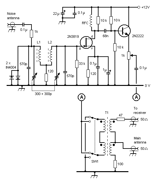
FIGURE 1 - Circuit diagram of basic noise canceller
Basic Noise Canceller Figure 1 shows my version of the VK5BR noise canceller, adapted for use on 136 kHz. L1; L2; and T1 were made using 25 mm OD 3C85 ring cores and wound with wire obtained from stripped-down internal telephone cable (the wire is plastic coated with a conductor size of 0.020 inch (25 SWG, or about 24 AWG). L1 & L2 are wound on separate ring cores and each is wound with 28 turns (see 'Alignment Procedure' below). The hybrid transformer, T1 uses 13 (+/- 2) turns, quadfiliar wound at about one twist every 20 mm. (If you are new to this type of transformer construction, see below.) The variable capacitor provides a variable phase shift of 0-180 degrees, and SW1 provides a further 180 degree phase shift, permitting an overall phase change of 0-360 degrees. The potentiometer is used to adjust the amplitude of the noise signal. In use, getting the exact settings optimised can take several seconds - but the results are well worth the effort! Alignment Procedure Firstly, disconnect the variable capacitor wire to L2, connect the noise antenna and monitor the noise output on the station receiver. Noise on 137 kHz should peak with the variable capacitor (now tuning L1 only) at about the centre position. (Note that the 'Q' of the circuit is quite low, so the tuning will be very 'flat', with a broad-band frequency response.) If the noise gets stronger at maximum capacitance: increase the value of fixed capacitance. If the noise gets stronger at minimum capacitance: decrease the number of turns on L1, one turn at a time, until resonance occurs near the centre position of the variable capacitor. You may need to remove up to 6 turns from L1. When this has been done, re-connect the variable capacitor wire to L2; then disconnect the variable capacitor wire from L1. As before, if the noise gets stronger at maximum capacitance: increase the value of fixed capacitance. If the noise gets stronger at minimum capacitance: decrease the number of turns on L2. Again, you may need to remove up to 6 turns from L2. Using the noise canceller A pair of switched noise cancellers Because the basic noise canceller requires different settings for each of my two
receive antennas (loop antenna/experimental vertical), I found myself having to adjust the
noise canceller quite frequently. My current arrangement involves two switched noise
cancellers in one box. I use a sense signal from my antenna switch to automatically
select the appropriate noise canceller for the chosen antenna. Also, I have now
introduced a 'mix' facility so that I can try to cancel two different QRM sources
simultaneously. |
|
Front View
|
Rear View
|
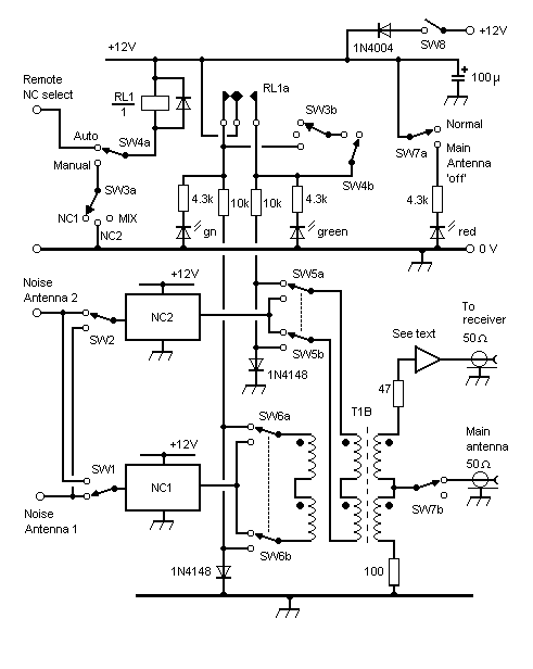
| FIGURE 2 - Circuit diagram of switched noise cancellers |
|
| Note that, in
the case of T1B, an extra winding has been added to couple the output of the second
canceller. Thus, for T1B, it is necessary to twist six wires together (at about one
complete twist per 20 mm) before winding the transformer. To make it easier to wind
T1B, I used a 42 mm OD 3C85 ring core.
(But a 25 mm core would probably have worked just as well.) To prevent interaction
between the phase and amplitude settings of NC1 and NC2, avoid selecting the same noise
antenna for both noise cancellers. Also, during construction, use 'point-to-point'
wiring around SW1 and SW2 to reduce capacitance between the two circuits. In the 'Auto'
mode, noise canceller 'NC2' is automatically selected when the main station antenna switch
applies an earth [ground] to the terminal 'Remote NC Select'. Compensating for loss through the hybrid transformer Of course, one thing leads to another! The 8 dB loss between the Main Antenna
port and the Receive port of the hybrid transformer (T1/T1B) meant that the usual S9
signals were only just reading S8 on the bargraph-type S meter of the FT707. To
compensate for this loss, a Receive
Pre-selector was constructed and connected at the Receive port as shown in
Figure 2. A resistive pad was used at the output of the pre-selector to set the
overall loss through the noise canceller to 0 dB. Construction of T1/T1B T1 and T1B should be wound with colour-coded wire, such as that obtained from stripped-down internal telephone cable, being sure to separate any 'twisted-pairs'. Using colour-coded wire makes it easier to identify each conductor when terminating the wires. First, the wires should be twisted together at about one twist per 20 mm. (Four wires should be twisted together for T1, and six wires for T1B.) Ensure that you allow enough of a 'tail' to terminate the windings, and use a cable tie to anchor the start of the winding. (The start of each winding is denoted by the black dot in Figure 1 and Figure 2 above.) Then wind about 13 turns around the ring core, using another cable tie to anchor the end of the winding. Click on the thumbnail to enlarge the picture of T1B.
During June 2001, many hours were spent at the bench with the dual noise canceller
pulled apart - soldering iron in hand - to help me better understand the present design,
and see how it might be improved. I came to the conclusion that: The dual noise canceller will now be restored as per the above design because, although
it may not be perfect, it continues to provide essential noise cancelling facilities at my
QTH. When time permits, I would like to build a new dual noise canceller with the
following improvements:
Further Reading A paper written by Derek Atter, G3GRO entitled 'A Simple Signal Canceller For
136Khz To Combat Loran or Other Noise Sources' can be found via the Crawley ARC web
site, and at: Another paper written by Derek Atter, G3GRO entitled 'Methods of Interference
Suppression Evaluation of Receiving Loops etc. And the MFJ 1025 Signal Canceller' can
be found via the Crawley ARC web site, and at: Use of the JPS Communications/Timewave Technology 'ANC-4' at 136 kHz. Notes from
GW4ALG's initial testing of this noise canceller can be found at: For details of a 50 MHz noise cancelling receiver see:
|
|