Reducing Noise In Home LF Receiving Installations
James V. Hagan, WA4GHK
It has generally been my experience that the AC line noise that is
encountered in most home LF receiving installations comes from two sources.
The first and most severe is by conduction through the AC supply line and
its safety ground. The second is by either inductive or electrostatic (or
both) near-field coupling to nearby AC lines.
Fortunately, it is fairly easy to reduce or eliminate both sources of
noise. First, the receiving antenna must be completely de-coupled from the AC line.
Filtering of the supply line will do no good unless the filter can be
provided with its own ground and not share any common connection to the AC
power ground.
Second, near field effects can be greatly reduced by locating the receiving
antenna as far away from the house and AC lines as possible. The distance
from the lines need not be great. If possible, explore your property with a portable receiver operating
from batteries to find the best location. If this isn't possible, select a
spot as far from the house and any overhead lines as possible. (In the last
place I lived, no place on the 110' X 110' residential lot was acceptable.
However, a spot quiet enough to allow reception of European LWBC stations and
WWVB existed on my neighbor's lot about 150 feet from my shack.) Once a good
location is found, install your antenna there.
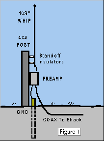 I use a Burhans Electronics E-field preamp with a 108" CB whip
antenna mounted on a 5' 4X4 pressure treated pine post. A 1/2" copper pipe,
10' long, was fitted into the ground near the post for a ground connection.
Power is fed to the unit through a buried coaxial cable from the
shack. This coax must not be directly or indirectly connected to the AC
distribution system. In practical terms, this means you cannot connect this
coax directly to the station receiver.
Many variations on this scheme are possible. For simplicity, the
preamp could be powered by batteries at the remote location, but I find it
more convenient to feed power from the shack. In either case, locate your
system in the clear as much as possible. Towering trees and very close shrubbery will lower the signal levels
dramatically. (Incidentally, E-field antennas don't work well indoors.)
By now you are probably saying, "OK, fine, but how do I get the
signal into my receiver if I can't connect the coaxial cable to it?" The
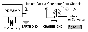
solution is to use an RF isolation transformer. In its simplest form, it
could be like Figure 2...providing your preamp has its own battery at the
remote location.
Once a system like this is working, you can prove its effectiveness
by a simple test. Tune your receiver to a weak signal, or a clear frequency
with no signal. Observe the signal level and listen for AC buzz. Little or
none should be heard, depending on the quality of your site. (My noise is
completely gone, but I have 3 acres to play with.) Temporarily connect a
short test lead between the body of the connector on the outdoor cable and
your station receiver. The noise will come up very noticeably, probably to
the original level you had before starting this project.
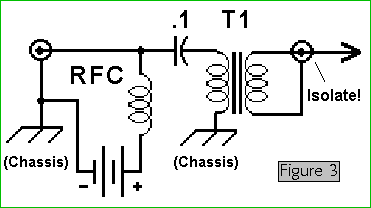
A better way is to use a battery supply located indoors so you can
conveniently turn it on and off. This is accomplished as shown in Figure 3.
The RFC keeps the battery from bypassing the signal to ground, and as before,
the output connector is isolated from the chassis ground.
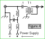
If you like the convenience of a small power supply rather than
batteries, you could do as shown in Figure 4, below. In this case the RFCs help
isolate the "noisy" AC supply from the remote location.
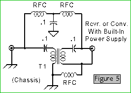
If your receiver is configured, or has been modified, to provide
power to the coax, as mine is, you can use the circuit of Figure 5, above. The RFCs
separate receiver ground from remote ground, and feed DC around the
transformer.
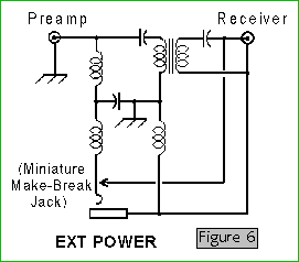
And finally, a universal model can be constructed that will use power
from the station receiver or an external source. It will switch between the
two automatically when external power is plugged into it (Figure 6).
In all of these designs T1 is wound on an Amidon FT-14-75 core. Wind
25 turns of any gauge magnet wire, #28 or smaller, snugly and evenly spaced
around the core. Wind 25 more turns between the turns of the previous
winding. No turns should be crossing or touching any other or isolation will
be reduced. Secure with household cement. The resulting transformer will be
good down to 10 kHz.
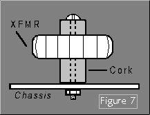 The entire circuit can be assembled in the smallest Bud mini-box or
Radio Shack 270-235 or equivalent. T1 can be mounted in the box by pushing a
wine bottle cork into its center. A machine screw passes through a hole in
the center of the cork to secure the assembly to the chassis. The cork will
probably be too long, so cut it in half.
Mount the input and output connectors in opposite ends of the box.
Note that the output connector must be insulated from the box. This can be
done by cutting a 1" square hole in one end of the box and covering it with a
piece of blank PC board material with the copper removed. A hole is drilled
in the center of the PC stock for the output connector. Verify insulation
with an ohmmeter.
The DC power jack is mounted in the top side of the box. Radio
frequency chokes (RFCs) are at least 3.9 mH with low DC resistance (30 ohms
or less; the less, the better). Exact value is not critical.
That's it. Remember, any connection between the AC system and the
remote cable or ground will result in noise. I have been using this system
or a variation of it for almost 20 years in several locations, with excellent
results. Good luck.
This article originally appeared in the June, 1994, issue of The LOWDOWN, and is protected under US and international copyright laws. Please obtain the author's permission before redistributing this document or reproducing it in any other form.
 Return to Longwave Antennas and Receivers Library.
 Go to Longwave Home Page.
 I use a Burhans Electronics E-field preamp with a 108" CB whip
antenna mounted on a 5' 4X4 pressure treated pine post. A 1/2" copper pipe,
10' long, was fitted into the ground near the post for a ground connection.
Power is fed to the unit through a buried coaxial cable from the
shack. This coax must not be directly or indirectly connected to the AC
distribution system. In practical terms, this means you cannot connect this
coax directly to the station receiver.


 The entire circuit can be assembled in the smallest Bud mini-box or
Radio Shack 270-235 or equivalent. T1 can be mounted in the box by pushing a
wine bottle cork into its center. A machine screw passes through a hole in
the center of the cork to secure the assembly to the chassis. The cork will
probably be too long, so cut it in half.
 Return to Longwave Antennas and Receivers Library.
 Go to Longwave Home Page