Noise is always a problem on LF. If the LF DXer lives in a densely populated area, chances are that one kind of noise is worse than all the others. That noise is from many of the electrical appliances that interrupt the power mains due to SCRs at each zero crossing of the 60 Hz signal. It turns out that the predominant frequency of this noise is 120 Hz. If you suspect that this kind of noise is causing your problems, look at the output of an amplified loop or whip antenna with a scope synced to the line frequency. You should see a periodic spike pattern with the spacing between the spikes equal to a 120 Hz repetition rate.
This noise is very strong at times, and I've tried several solutions to attenuate it. Steerable loops are sometimes able to find a null in the noise and avoid the worst of it. I've tried nulling it with the ANC-4 phase nuller. I haven't had too much luck with this. It can reduce it some, but not enough to really help much. The one thing that does work well for me is a synchronous blanker. These were written up several years ago in The LOWDOWN. See, for example the issues of June, 1983, and November, 1987. This last article by Sheldon Remington has a useful sync generator circuit. This article is now available in the reprints of Sheldon's articles, "On The Art of NDB DXING," reprinted by Stephen McGreevy. I strongly recommend this series of articles*.
Going back to the noise, if you can get a look at it on your scope, notice how little time it really is present. The noise spikes are very narrow, and there should be a lot of good signal between them. That tells us that a blanker should be effective against it. Blankers have two components:
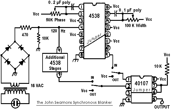
The sync generator from Sheldon's paper is what I'm using to generate the blanking signal. It was easy to find parts for it, and building it was simple. It has only two controls: Duration and Phase. I recommend building the generator in a separate well screened box, since it will generate some noise on its own if this is not done. I generate and control the noise with one box, and then have a small box with the gate circuit that the antenna wire passes through.
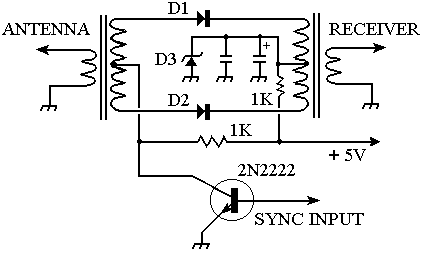
The gate circuits discussed in LOWDOWN papers used two diodes in an unbalanced configuration. I thought a balanced design would be less prone to generate transients, and this has proved to be true. This new circuit is mainly copied from blanker designs used in shortwave receivers in the IF strip. In this application, it will be used in the antenna line. The transformers were derived by CAD modeling of the circuit to give the best signal transfer, and using germanium diodes also causes less signal loss. The circuit of the gate follows.

The Circuit. This is a schematic of the gate circuit for noise blanking. Diodes D1 and D2 are 1N34s, matched as closely as possible. I found that these germanium diodes gave a higher level of signal than silicon diodes. Diode D3 is a 3 volt Zener diode. The exact value is not too important, just something less than 5 volts. Both resistors are 1000 ohms. The capacitors are .1 mFd monolithic and 10 mFd tantalum. The input and output transformers are identical and consist of primary coils with 3 turns, secondary windings of 12 turns center tapped, all wound on FT50-75 ferrite cores.
How it Operates. When noise is not being blanked, the anode of each diode is at a higher positive voltage than the cathode (thanks to the Zener diode), so forward conduction takes place and the signal path represents a low resistance. When the 2N2222 transistor is switched on during blanking, the diode anodes are brought very close to ground, and are therefor reverse-biased into cutoff. This way, a single switching device can reverse the polarity of bias seen by the diodes.
Adjustment. After you get the circuits built, look at the sync signal with your scope. You'll get a feel for how the two controls change the width and position of the blanking pulse. When the pulse is +5v, the gate is shut (no signal gets through). To use the blanker, start with a pulse width of a little under 50%. Then move the pulse with the phase control until the noise disappears. Now, reduce the pulse width while changing the position until a minimum width is found. At this position, the maximum amount of signal is being let through, while noise is being canceled.
I've found the synchronous blanker will handle 120 Hz spike noise better than anything else I've tried. It can take 60 to 80 dB of noise out easily. It will leave some 120 Hz modulation on the signal, but this is a small price to pay for getting rid of that much noise.
*Sheldon Remington's reprints are available from:
Stephen McGreevy
604 North F Street #1
Lakeview, OR 97630
e-mail vlfradio@triax.com
Blanking generator circuit from "On The Art of NDB DXing;" The LOWDOWN, November, 1987:

(This document is protected under U.S. and international copyright laws. Obtain the author's permission before distributing in any form.)
Return to LF Receiving Library.