Results
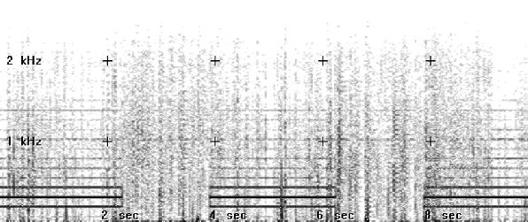
Here are the results of my first cut at a hardware hum blanker. I recorded an approaching storm with my whistler receiver (4/30/2000).
I then passed the recording through the hum blanker and into GRAM. Here the recording had the 60Hz notch filter in place but did not have the high pass filter in place.

About every two seconds I switched the hum blanker in and then out of the circuit. The removal of the (odd) 60 Hz harmonics is dramatic.
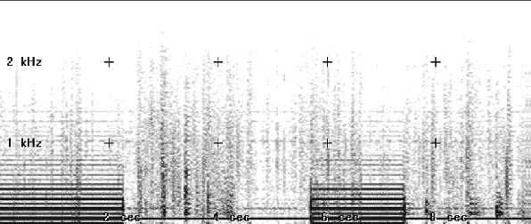
In the next example, I switched out the 60 Hz notch filter as well. Even harmonics of 60Hz are now apparent, probably from overloading the FET front-end.

Again, I switched the humblanker in and out.
The downside
When the hum blanker is in circuit, there is a distinct ghosting on the sferic signals. This effect is apparent in the images above. These are quite apparent when listening to the signal. However, whistlers sound fairly normal. The device can be used in real time, but is probably best used for processing recordings.
The circuit
I have built a Radio Shack Mini Echo Mixer kit (990-0239, based on a BBD chip) and modified it to build the hum blanker. The modifications included changing the feedback path, making the delay clock-frequency variable, and raising the cutoff frequencies of the low pass filters.
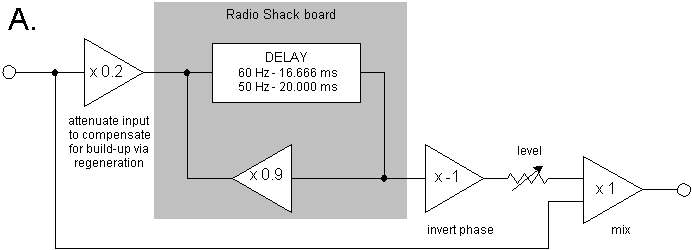
The basic idea is to use a 16.666 ms delay and recirculate the signal in phase at a gain of about 0.9. This reinforces the 60 Hz harmonics and deemphasizes everything else. The result is a comb-filtered 60Hz with harmonics up to the frequency limits of the delay system.
Because the interference is "static" one cycle is pretty much like the next, so the delayed signal closely matches the input interference from moment to moment. This signal is mixed out-of-phase with the original signal to null the hum. The block diagram A. below shows the overall circuit design.

The schematic for my added circuitry is here . The modifications to the Radio Shack Mini Echo Mixer Kit follow. Part numbers reference the schematic supplied with the kit.

When the hum is dialed out, configuration A. has significant regeneration noise from the delay board. So, from a live listening perspective, I find configuration B. more pleasing than A. In either case, I use the 60 Hz notch filter in my receiver , but disable both the high and low pass filters. If I disable the notch filter, the 60 Hz hum is so strong that is overloads the signal chain. I turn off the headphone amp and feed the hum blanker from the record out of the receiver.
Bottom line, the unit makes urban listening feasible but is emphatically NOT like listening in a quiet location!
The unit
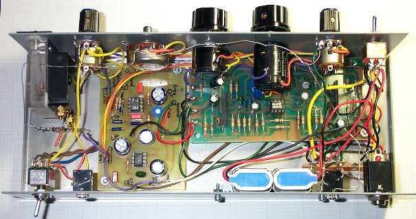
Here are photos of the front panel and the interior of the unit. The meter is used to adjust the drive to achieve good S/N with the delay board.


The Radio Shack board is to the right and the additional circuitry I added to the left. A TL082 is used (1) to mix the dry and delayed signal, and (2) drive the meter. An LM386 is used to drive head phones. 3.5 mm jacks are provided for input and record out. The 1/4" jack is for the phones.
The switch to the lower left changes the mode between the two configurations shown above. Contact me for details if you want to add this feature.