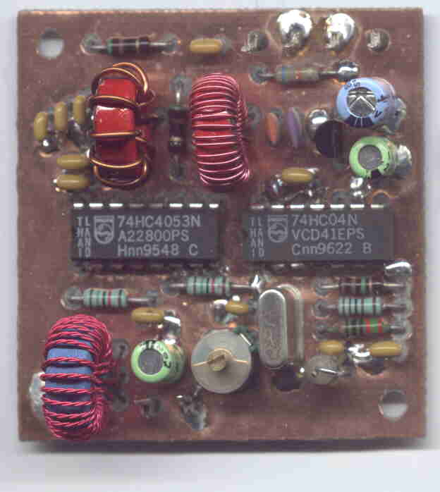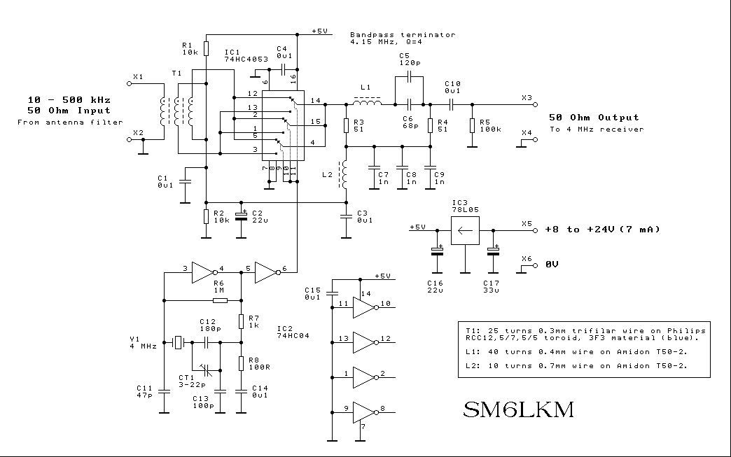

This converter uses a 74HC4053 as the mixing element. It simply reverses the polarity of the incoming RF at the local oscillator rate. The principle is the same as in the case of diode ring mixers. The input signal is multiplied by either +1 or -1. All three switches in the 74HC4053 are connected in parallel in order to reduce the switch loss resistance. The 'HC4053 switches like an SPDT between the opposite sides of a phase reversal input transformer.
'HC4066 based designs, especially those connected as a "classic" ring mixer, need a few hundred ohms of system impedance to avoid intolerable switch losses. The "parallel 4053 circuit", on the other hand, seems to work quite well in a 50 ohm system.
I am using an IC-735 which is quite deaf on 136 kHz. When I connected the 'HC4053 converter and tuned the IC-735 to 4.136 MHz instead, the sensitivity was greatly improved even though the converter has a few dB's of conversion loss (perhaps -10dB, no measurements have been made...).
The PCB layout is available in GIF format. The board size is 2 x 2 inches. (Sorry about the GIF format but that's the best I can do with my old CAD program... I hope you will be able to scale it for printing).
Download PCB layout (layout.zip, 21K)

Hit count: 8933