
![]()
OZ1MAS
Last updated : 28-11-01 08:17:14
![]()
MY NEW VLF
PROJECT. ![]()
Now I have been using and testing my first BBB-4 VLF reciever for about a year and liked to rebuilt all the reciever for some modifications of my own, here are two pictures of my old and new reciever.
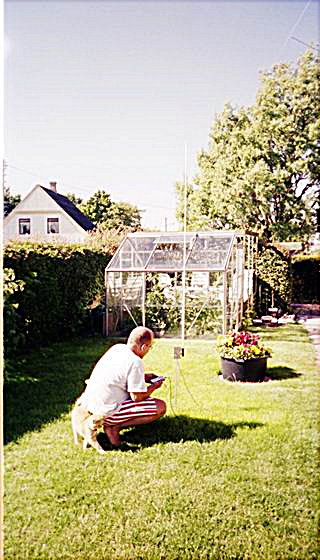
(Oldreciever) (Newreciever)
First I would like to tell a little about the BBB-4 VLF reciever made by Stephen P McGreevy, the BBB-4 stands for "Bare bone basic version 4" and is a kind of "keep it simple VLF reciever" for the beginner.
The BBB-4 reciever are made for recieving naturally occurring radio phenomenas in the frequency area 200 Hz. to 11000 Hz. The reciever are a heigh impedance FET E-field reciever for small antennas size 1-3 meters.
The tecnical data for my newbuilt VLF reciever is like this:
Input Lowpass filter stops about 23 KHz.
PI Filter stops about 6 KHz.
Current about 8,4 V / 25 mA.
When I prepare to built my new reciever I had some wishes I like to do better in this version:
Better antenna connection.
Speakeramplifier.
Control of input level at every single stage.
Led for On/Off (And finding the reciever at night).
![]()
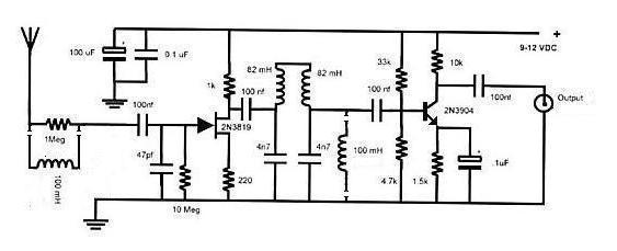
Here are the schema for the orginal BBB-4 reciever and the class "A" preamplifier, the two 100 mH coils in the input and in the PI filter are mods and not a must.
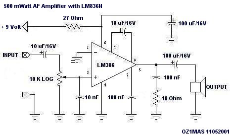
This are the schema for the LM386 AF amplifier.
![]()
Here there are some pictures of the 3 PCB I made for the reciever.
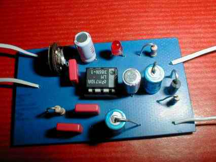
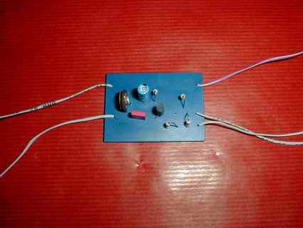
(500 mWatt LM386 Amplifier) (BC546 Preamplifier)
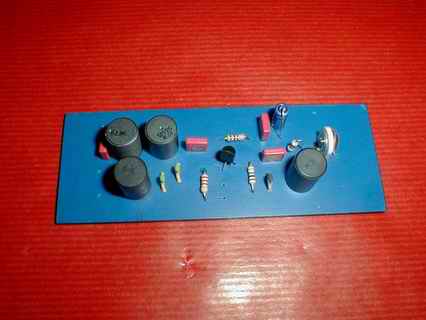
(VLF reciever with J310 FET)
The LM386 AF amplifier is a for me wellknown and simple amplifier used for many projects, this is made for 200 times gain, thats lot of power for a small speaker or headphones.
The Preamplifier are nearly the orginal from BBB-4 but in this version I control the output with a 10 KOhm variableresistor, it was not possible for me to get a 2N3904 but a BC546 transistor can do the same job, the reason for control of the output is that I liked to control the recording level to the taperecorder.
The VLF reciever & PI filter are also nearly the orginal BBB-4 with all mods included, I use a 500 KOhm variableresistor for control of the input, it was not possible for me to get a 2N3819 but a J310 FET transistor work as well .
The idea with a LED to indicate On/Off is good you remember to turn the reciever off and one early morning some time ago, I had some problems to find the reciever in the dark, it's easy to see a LED in a dark night.
After testing the PCB I wired them like this for the last test.
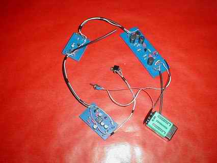
(Test of the reciever)
The loose shielded wires are for tape output and antenna.
I choosed a waterproff solidstate moulded Aluminium box for safety of the PCB and for good RF shield.
Now it was time to make holes in the moulded aluminium box, I choose to make it like this.
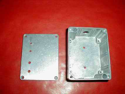
(PCB's placed in the box) (Holes drilled in the box)
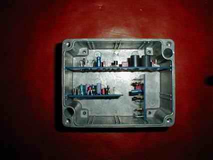
Now it was time to mount screws and PCB's in the box.

(Inside look in the Reciever)
Finally some pictures of the reciever box when it's ready for field test.
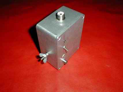
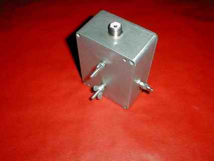
(Front) (Back)
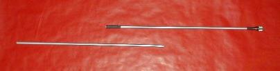
The two screw's at the back is for a aluminium tube to set into the ground and the screw at the left side are for ground cable if used, antenna are a one meter 8 mm aluminium tube. mounted in a PL 259 male connector with some 10 mm airhose as isolator and some crimpflex to complete the finish, I have made two antennas the first at one meter and the other at two meter to use at more silent areas.
After the first fieldtest of my new BBB-4 VLF reciever I was very happy for the new design and mods I have made in this version.
Hope to hear from a lot of people with comment's or interess for my new reciver, also thank's to Stephen G McGreevy for his design of the BBB-4 Reciever.
![]()
![]() Modification : Instead for the 1 Mohm resistor / 100 uH coil in the inputstage, use a
500 Kohm resistor and a 500 Kohm variable resistor, now there will be mutch more
input to ajust, my BBB-4 reciever works now just as good with 1 meter antenna as
with 1,5 meter before the mod, offcause the hum also get's stronger.
Modification : Instead for the 1 Mohm resistor / 100 uH coil in the inputstage, use a
500 Kohm resistor and a 500 Kohm variable resistor, now there will be mutch more
input to ajust, my BBB-4 reciever works now just as good with 1 meter antenna as
with 1,5 meter before the mod, offcause the hum also get's stronger.
 Next
to come : I have built another version of the BBB-4 reciever this time it's made
to cover the frequency range 200 Hz. to 25.000 Hz. in the inputstage and 60.000 Hz
in the PI-filter this time I plan to make it more portable then last version.
Pictures and schemas will be at my homepage in December, I still have to make
some last field test.
Next
to come : I have built another version of the BBB-4 reciever this time it's made
to cover the frequency range 200 Hz. to 25.000 Hz. in the inputstage and 60.000 Hz
in the PI-filter this time I plan to make it more portable then last version.
Pictures and schemas will be at my homepage in December, I still have to make
some last field test.
![]()
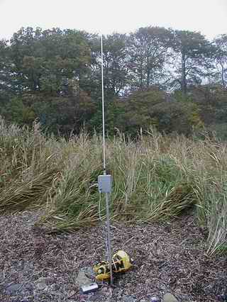
Here are a picture of the reciever in the field at Knudskov and one of my daughter with the reciever as portable.
(550502N 0114865E)
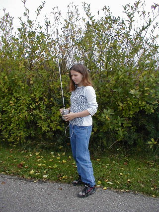
(Susan with the reciever as portable)
![]()

Send comments to : oz1mas@qsl.net
![]() Back to homepage.
Back to homepage.