STATION SETUP
and receiving techniques 1
by IK1QFK
The equipment necessary
to listen VLF signals below 22 kHz is different from the classical Ham
radio station because the low frequencies are received directly, without
frequency conversion: the heart of the station is the computer which allows
you to recognize signals, translating them in graphical form.
The incoming signal is
applied to the Sound blaster input via filtering and conditioning. Here
some fine programs do the signal analysis. There are many programs
to make spectrograms in real time with a computers , but I prefer and suggest
"Spectrogram"
by Richard HORNE. It is freeware and the continuos upgrades of the author
makes it a "live" software. "Spectrogram" is easy to use, runs correctly
on many PCs (at least from Pentium 75 up) and the results are excellent.
Back to my radio shack. These antennas are usually
connected directly to Mic-Input (30mV on 10kohm) of a Stereo Cassette Tape
(CT300 PIONEER) or to Line-INPUT (300mV on 4.7kohm) of the same. The Line-Out
of CT300 is connected to the Line-Input of SoundBlaster Card and when the
tape deck is in REC or in REC/PAUSE the signals can be set at the correct
level by the Mic-Gain control. The antennas are placed outdoor (of course),
about 70m from buildings and electric lines.
ACTIVE
RECEPTION SYSTEMS:
RS4
NASA-INSPIRE
with 8m whip (in figure shown
with a 75cm whip). Active Electric Field Receiver with 100Hz-10kHz band.
Electric circuit at INSPIRE
web site.
Good results when conditions are
good; easy to build, excellent to begin this activity and for field days.
Output is connected directly to the CT300 by 70m of coaxial cable. In crisis
during the storms (blocked by static DC fields). |
 |
Active Magnetic Loop
19 turn/75cm (0.8mH). Magnetic
field receiver with a 100Hz-22kHz band. Homemade, design and costruction.
Results are similar to RS4 but better in critical situations, like in presence
of strong 50 Hz harmonics. Output is connected directly to the CT300 (Line-INPUT)
by 70m of coaxial cable. Thanks to low output impedance it can be used
even with an headphone, with a strong output level.
The antenna can be replaced with
larger loops of similar inductance, like a square loop of 1.7m side/11
turn or even more with triangular loop of 6 turn of 8.4m base and 5m high
(with a gain of 22 dB in comparison to my circular loop). Good results
also during the storms. |
 |
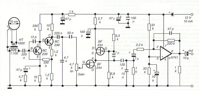
ACTIVE MAGNETIC LOOP, amplifier
schematic |
PASSIVE RECEPTION
SYSTEMS:
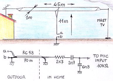
Marconi vertical antenna,
passive T antenna 11m high with
45m double top. Born to send and receive signal at 137 kHz (european amateur
LW Band) and now used also to receive the electric vertical field in a
2Hz-22kHz frequency range. The performance is similar to the RS4 but the
S/N ratio is much better. Connected to the mic input with a series of 2.7
kohm and 2.7nF, and 6.8 nF in parallel, see picture.
Dangerous
during the storms (GROUND IT!) |
 |
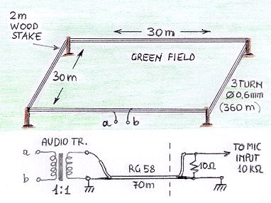
Horizontal Square Loop
30mx30m, 3 turns of 0.6 mm insulated
wire (360m), fixed at the top of 4 wooden poles. Connected to the MIC input
through an audio transformer, with a 10 ohm resistance in parallel (mic
input side). Suitable to receive 1Hz-6kHz band. Good results also during
the storms. |
 |
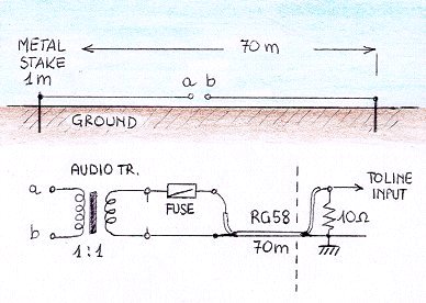
Earth dipole 70m
2 metal
stakes of about 1m, planted in ground at about 70m of distance, in North-South
direction. Connected to Line-INPUT of CT300 by an audio transformer, 10
ohm load and 70 m of coaxial cable. Suitable to receive 1Hz-22kHz band
with discrete results (strongly conditioned by 50 Hz harmonic noise). Good
results instead in a 22kHz-750kHz band with strong signal and low noise,
using VLF converter. Dangerous during the storms. |
 |
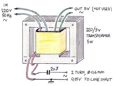
Transformer on the electric
line,
small and cheap 220/9v 5W transformer,
ideal to monitor signals on the electric line (!...see later). Useful to
verify if signals received with precedent antennas are carried by electric
lines. |
 |
To complete the shack I also
have some more usual equipment: DATONG VLF Converter, DRESSLER ARA
30 active antenna, YAESU FT757GX and various dipoles.
... but this is another story.
Return to the index


