Overview
This induction magnetometer was constructed
to monitor the geomagnetic activity of the earth in the long term. The
results will be used to study the effects of the solar storms and other
programs that require long term monitoring. An induction magnetometer is
essentially a loop antenna that converts an oscillating magnetic field
into a voltage.
Construction
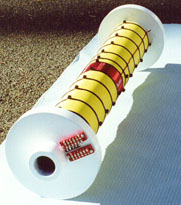
The instruments 630 mm length coil, was wound on a piece of 754 mm hollow bar. This bar (ISO 2938) has an external diameter of 62.85 mm with an 40 mm hollow core. Hollow bar was chosen so various steel cores could be evaluated. Both ends of the bar were fitted with a 200 mm by 25 mm diameter phenolic resin (Tufnol Carp) machined plate.
Onto this bobbin was wound 100,000
turns of 0.315 mm (#31 SWG British) (#28 AWG) polyester insulated copper
wire. The cooper wire weighs 16.3 kg's. This equates to approximately 14
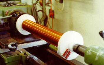
kilometres of wire. It was wound on a normal machine lathe with careful
attention to the layering of the copper wire. Every six or so layers a
sheet of "DMD 0222" was place as a stabilizing layer. This kept the coil
windings even. Additionally, every three layers a coating of (Incralac)
varnish was applied.
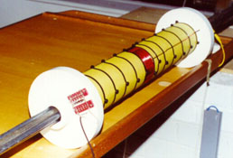
The final outside finish, was a layer
of insulating "DMD 0222" sheet. This material is found in workshops specializing
in winding transformers. The coil was make from smaller lengths of wire
that were joined to form the large coil. There were five outputs. The total
coils resistance is 4812 ohms.
Coil Winding
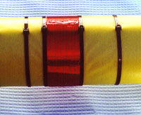
On the outside of the coil was placed
a calibration coil. Its 41 turns of 1 mm diameter wire. This allows for
a relative frequency calibration to be performed.
Calibration Coil
Core Material
The final core material consist of
4 lengths of 3 meter by 12 mm rebar iron rod plus three lengths of 610
mm by 12.7 mm "Hy Mu 80" material. The "Hy Mu 80" material has exquisite
magnetic properties.
Core Material
Calibration
With the use of a frequency generator,
oscilloscope and the calibration coil a relative calibration curve was
established. Then using a published geomagnetic "Pc3" event a good estimate
of the absolute calibration curve was found. It should be noted that the
upper end of the graph is due to the amplifiers response and the lower
end is cut short due to the frequency generators limits. The lower end
can be extrapolated.
Electronics
The output of this coil is feed into
a high gain amplifier with low pass filtering. This is then monitored by
a 16 bit A/D amplifier via a logging computer. Each bit of the A/D represents
0.0000153 volts.
Frequency Band
My principal interest is in the Ultra
Low Frequency band (ULF less than 3 hertz).