|
| GW4ALG
Loop Antenna Tuning Unit The Loop ATU consists of a capacitive matching network (3 capacitors) and a toroidal 4:1 balun. The balun is made using 18 bifilar-wound turns on a 58 mm (overall diameter) Philips toroid of 3C85 material. The high impedance side presents a 50 ohm load to the transmitter/receiver. The capacitors used are from the Philips 378-series and Philips MKP-series of high current capacitors and the SWR is very close to 1:1. |
 |
| The ferrite
balun is used to maintain, as far as possible, the balance of the antenna and hence reduce
local common mode noise being coupled to the receiver. It works! As with most
housing developments in the UK, the garden is quite small. So noise levels from all
sorts of electrical appliances can easily reach S7 during the evenings on a marconi-fed
antenna. Local noise levels on the loop are, typically, about 10 dB lower relative
to my marconi-fed antenna. Note that, from a receiving point of view, this ATU provides very little immunity to out-of-band signals. In particular, HF signals may be coupled to the receiver front end with very little attenuation. Hence use of this ATU still requires a good pre-selector or band-pass filter in the 136 kHz receiver. |
|
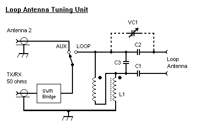 |
Typical values (for a delta loop of 70 m
perimeter): C1; C2: 18,000 pF; C3: 0.15 uF. Use high voltage, high current capacitors if the tuning unit is to be used for transmitting. L1: 18 bifilar turns, wound on a Philips 58 mm OD 3C85 core ring core. |
| Fine
Tuning the Loop Antenna Where the DC resistance of the loop is greater than 2 ohms, or if the loop is used for receive purposes only, VC1 will not be necessary. For transmitting applications where the DC loop resistance is less that 2 ohms, the reduced bandwidth will require the use of VC1 to accurately resonate the loop. For a 65 m loop, a 1000pF wide-spaced variable capacitor will provide a tuning range of +/- 600 Hz (1200 Hz overall) at 136 kHz. Included within the tuning unit is an SWR bridge to check for resonance, and an antenna switch (RS Part Number 316-844) for selecting a second antenna. 50 ohm coaxial cable (UR67) is used for equipment interconnections. |
| A 'strapping field' of screw terminals was used with a number of capacitors to allow rapid adjustment of C3. The values given in the circuit (at right) will permit a wide range of loop sizes to be matched to a 50 ohm transmitter/receiver. | 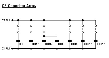 |
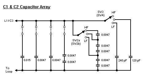 |
Switches SW2a and SW2b are ganged and provide coarse tuning of C1 and C2 capacitor arrays. Fine tuning of each 'leg' of the loop is provided by switches SW3 and SW4, which are not ganged. |