Visited 4502 times.
Description
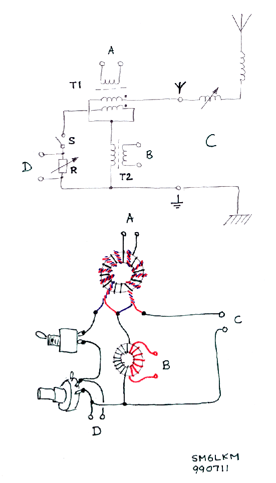
This is a simple bridge intended for measuring the feedpoint resistance of LF antennas. The "antenna ground" has to be isolated from "other grounds", such as the mains protective ground in order not to disturb the true ground loss resistance of the antenna system. This is accomplished by inserting the isolation transformer T2 in the circuit. This isolation makes it possible to use, for example, a grounded oscilloscope as a bridge balance detector.
The transformers can be wound on ferrite toroids. The only important thing is to wind T1 as symmetrical as possible. The secondary winding (with phasing dots in the schematic) on the prototype was made by winding 18 bifilar (twisted) turns evenly spread around a 25mm 3F3 toroid. The primary winding (port A) was then wound with 18 turns of thin wire between the twisted turns. Placing the two windings on opposite sides of the core, as on T2, is perhaps even better due to reduced capacitance.
T2 was also wound on a 25mm 3F3 toroid core. The windings of T2 have 18 turns each. The windings are on opposite sides of the toroid core in order to minimize the capacitance between them.
The number of turns, core material etc. is not important. However, it is a good idea to aim for a winding reactance of a few hundred ohms. The sensitivity will suffer if the inductances are too low.
The potentiometer R should have a few hundred ohms (NOT wire wound!). A 150 ohm cermet potentiometer was used in the prototype.
It is important to feed the bridge with a pure sinusoidal signal. Harmonic content will make it impossible to get a bridge null.
The ports A and B can be interchanged i.e. the signal generator can be connected to B and the detector can be connected to A.
Operation
