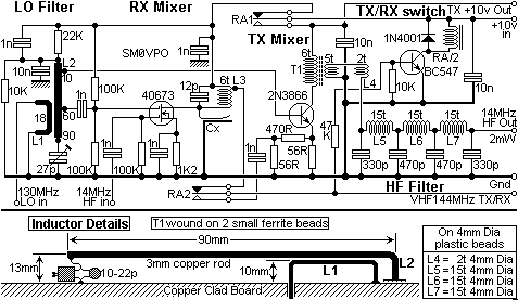

This little circuit is a transmitting and receiving converter (transverter) that converts a FT290 or similar multimode handheld transciever to the 14MHz amateur band. The project is a single board module that needs an external local oscillator, for example, the VHF harmonic oscillator (or QRP VHF FM TX) LO for transverter project. It should be a relatively simple matter of scaling coils and caps to convert other bands. You may choose to omit the TX/RX switching and the TX mixer and use this unit as a receive converter giving 14MHz - 16MHz coverage on a multimode VHF receiver.
If you choose to use the full transverter circuit then you will be pleasantly surprised at the spectral purity of the transmitted signals. All unwanted spurious signals and even oscillator breakthrough are well under -75dB at the output terminal. The HF TX output from the unit is about 2mW and will give a full ten watts from my 10-Watt HF linear amplifier. The VHF rig must be of the type that also delivers +10v DC at the antenna socket on transmit. This is true of the FT290, C58 and most multimode handportables.


The local oscillator (LO) input from the previous project is very clean, but is here filtered again by L1. A low impedance tapping on L1 feeds the TX mixer transistor (2N3866 or 2N4416). A higher impedance tapping feeds the G2 of a dual-gate mixer transistor. The numbers beside L1 indicate the number of millimeters for the tappings, measured from the Earthy end of the rod resonator.
The receiver mixer has the incoming HF fed into the G1 and the resultant VHF 144MHz signal is filtered by L3. The tuning capacitor across this coil is selected so it is just a little HIGH of resonance. A bit of wire soldered to the hot end is then placed close to the PCB groundplane and adjusted for exact resonance. The passband of this stage is about +/-5MHz so the tuning does not have the be precise. The coil is self supporting. No HF preamp was found necessary so the HF input to this stage is direct from the HF antenna, via the external TX/RX relay, RB/2.
The TX mixer is an ordinary bipolar transistor. This is because there are RF signal levels of well over 10mW coarsing through this stage, so a small VHF power transistor gives far better linearity. The HF output from this stage is via T1; a small transformer wound on two VHF ferrite beads. Grade and size is unimportant. If the wire fits, use it!
The Output of the TX mixer is filtered. The filter L5, L6 & L7 has a very sharp knee cutting off at about 15MHz. The signal is over -3dB down at 16MHz so this filter is right on the edge of the coverage. Since anything more than 14.350MHz is out of band it is illegal to transmit up there anyway. This filter does not affect receive. The output from the filter is 50-ohms at 2mW which is more than enough to drive my 10W HF Power Amplifier (linear) project to give full 10-watts output. The filter L5, L6 & L7 is also duplicated at the output of the Power Amplifier.
A BC547 is switched ON by meansof the DC content from the VHF TX/RX antenna socket. This transistor energises a 10-volt relay, RA/2 having two changeover contacts. One contact set routes the VHF TX/RX antenna signal to the TX or RX mixers, as appropriate. The other contact routes the input 10-volts supply to the TX or RX mixers, as appropriate. The TX mixer +10-volt supply is also used to energise an external TX/RX relay.

The prototype was also built on a bit of un-etched copper clad PC board with a central divider. All components are self supporting, but the RX mixer was built on a central divider that screened L1 from the TX mixer and HF signal circuitry. The whole mixer board should be screened, exactly as the VHF harmonic oscillator (or QRP VHF FM TX) LO for transverter project, in fact, the same board size and screen tin construction was used. When I have finished moving house I will add photographs to this project.

Very best regards, and have fun, from Harry - SM0VPO