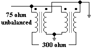
An old typical usage of the balun was (and still is) with TV antennas. The folded dipole is part of a yagi antenna which looks something like a pole with rods set across it at right angles. The second last one is folded into an oblong or rectangular shape. A folded dipole exhibits two important characteristics (a) its bandwidth is good for over an octave (e.g. 50 Mhz to 100 Mhz or say 120 Mhz to 240 Mhz) AND its characteristic impedance is a more or less a constant 300 ohms.
In earlier days extensive use was made of 300 ohm twin lead ribbon cable to feed the signals to the TV receiver. BTW you can use just a length of 300 ohm ribbon cable to make a folded dipole.
When colour (or color if you prefer) TV was introduced the ribbon cable often created problems which could be rectified by the use of co-axial cable. This is not strictly correct because coax had earlier uses in TV because of other problems such as ghosting which became intolerable with the introduction of colour.
Now 300 ohm coax can be and is made. However 50 and 75 ohm cable is preferred for a variety of reasons. Our folded dipole also exhibits a "balanced" feed characteristic whilst coaxial cable has an "unbalanced" characteristic. Two problems. Each solved by the use of the balun.

Perhaps we should have some clarification about this balanced versus unbalanced jazz. Mentally visualise it this way. If we have a plus 12V D.C. supply with ground return. That could be regarded for our illustrative purposes as the unbalanced 75 ohm input. On the other hand we could a symmetrical power supply referenced to ground which provides a + 12V D.C. AND a - 12V D.C. voltage. The only difference is we are dealing with R.F. which of course is very high A.C.
A practical 300 / 75 ohm balun would consist of four pieces of 0.4mm wire wound 2 1/2 turns through a balun core (look a bit like binoculars). In so doing we have achieved our two goals, (a) the impedance transformation and (b) gone from unbalanced to balanced.
That's all folks. Please
email me.
http://my.integritynet.com.au/purdic/
URL: http://my.integritynet.com.au/purdic/baluns.htm
Email to: Ian C. Purdie
This site was entirely written and
produced by Ian C. Purdie*
Created: 28th October, 1999 and
Revised: 29th October, 1999
****