| Make
That Perfect Dipole
by Harry
Lythall, SM0VPO
The dipole
antenna is perhaps the simplest and easiest antenna to erect,
but I have still seen installations where basic mistakes have
been made. So here is some reference data, pointers and ideas
that may help you.
To me, QRP
means transmitting and establishing contact with other stations
using a reasonable amount of power. With typically less than ten
watts available it is vitally important to ensure that the antenna
system is not wasting energy. Firstly, the antenna must be cut
to the right length and matched to the transmitter.

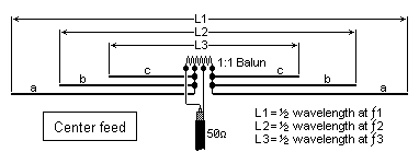
The balun
shown above is required to match the ballanced antenna to
an unballanced feeder. Typicaly 5 + 5 + 5 turns of thick enamelled
wire are wound on a ferrite ring, the three coils are connected
in series from the start of one winding to the end of the next.
L1, L2 and L3 are for resonance on three different bands. L1 (a+a),
L2 (b+b) and L3 (c+c) are equal to:

Add as
many dipoles as you need to form an antenna system for the
bands you want. Naturally, there will be a limit, but this is
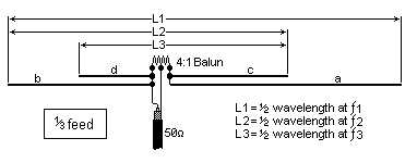
a practical limit. You can reduce the amount of wire you need
for a multiband antenna by using an "off-center" feed point and
using a 4:1 balun:

The bands
must be twice the frequency of the previous band with this
method. For example, if a=60 meters and b=30 meters, then a+b
will resonate at about 1.8 MHz. If c=15 meters then b+c will resonate
at 3.5MHz. If d=7 meters, then c+d will resonate at about 7 MHz.
This technique can reduce the amount of wire you have to buy.
You can
reduce the physical length of a dipole by inserting a coil
in one of the leads, close to the feedpoint.

A short
length of plastic conduit pipe is ideal for light antennas,
but for heavier guage antenna wire I steal those plastic spacers
from between bread-trays in the local supermarket.
The QRP antenna must be as efficient as possible, so use as thick
a wire as you can afford (or get away with). Use insulators at
the ends. The impedance at the ends of a resonant dipole is VERY
high so you cannot just tie the wire around a tree or something.
Heavy coat buttons make good insulators for lighter antennas,
but use more than one in each end. Finally, a multi-band dipole
may not necessarily be cut for more than one band, cutting the
elements for, say, 3.5 MHz, 3.6 MHz, 3.7 MHz and 3.8 MHz will
give good results across the complete 80 M band.
Ok then,
that is all I have to say about the dipole antenna for the
moment. A lot of it is just good sense, but perhaps you may have
learned something from this little presentation.
Editorial
note: Even if this describes
a transmitting antenna, all that is said goes for receiving antennas
as well; except that you do not have to be concerned a lot about
matching and radiated power and stuff like that. But any perfect
transmitting antenna is also a good receiving antenna.

This is only one of lots of interesting radio and antenna projects
that Harry
Lythall, SM0VPO, in Upplands Väsby, Sweden, has
to offer on his web site. A visit is highly recommended.
|


