|
Amplifier
for internal antennas
by Bruce
Carter
The first
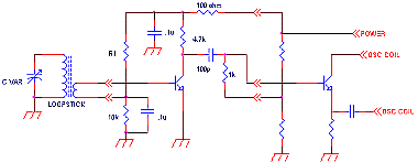
figure shows the antenna input circuitry of a typical AM radio.
There may be some slight variations on this, but the circuit described
here will compensate for them.
AM
radio input circuitry before the modification
The author described assembling this circuit on a 1"*1"
perf board, I actually laid out a small PC board with excellent
results. In this era of surface mount components, I think a much
smaller version can be laid out on a PC board, allowing this circuit
to be put inside even the smallest radios, such as Walkmans. If
I do such a board, I will put the PC board artwork here.

AM radio input circuitry after the modification
(click here for larger
photo)
From the
article: After the booster is built, open the radio and locate
the antenna. Trace out the secondary winding (it does not
go to the tuning capacitor!) and snip the leads. Connect these
leads to the input of the booster. Run leads from the booster's
output to where the antenna secondary went. You must finally connect
up the power and ground and mount the board to be finished. When
that is done, turn on the radio and tune in a weak station above
1400. Adjust the set's antenna trimmer and you are done.
To the
above I would add:
Any NPN transistor can be used. The author used a 2N3904, but
a 2N2222A should work just as well. A good, low noise transistor
would be even better.
Some radios only have three connections to their ferrite bar antenna:
the antenna connection to the tuning capacitor, ground (two wires
twisted together) and secondary (the smaller number of turns).
In this case, treat the twisted wires as ground, and the secondary
wire as the base connection to the transistor. The transistor
will then receive its base bias from the radio.
R1 changes
with the supply voltage. If your radio is 9V, use 56K. If it is
6V, use 47k. If it is 3V, use 33k. The goal is to bias the collector
of the transistor to one half the supply voltage.
The schematic
shown is for a negative ground radio. For a positive ground radio,
subsitute a PNP transistor.

This page is based on the article: "AM Radio
Booster" by Gary McClellan, Radio Electronics, April 1972, page
25.
|


