Translation tools from SYSTRAN
Translate your documents within seconds with Try SYSTRAN Personal!
LAST MODIFIED:
Sunday, 21-Apr-2002 22:05:35 EDT
We will start with low pass filters ( LPF ) because they are the basis of other filter designs. High pass or band pass filters are often simply transformations from low pass filter designs.
Perhaps the simplest low pass filter is the classic butterworth pi network design where the reactive elements are of a constant impedance e.g. 50 ohms and the design Q = 1.

Figure 1 - butterworth pi network low pass filter diagram
This example is most frequently used in the output of a transmitter to minimise harmonic output and eliminate QRM. As with all simple designs there is a limit to the benefit to be gained. If such a filter were designed with a cut off (Fc) of 7.5 Mhz the attenuation only becomes significant well away from that frequency.
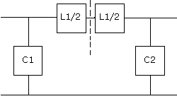
It is simply two L networks added together like this to form a low pass pi network filter:

Figure 2 - two L network low pass filters
Where the reactances are C1 = C2 = 50 ohms each and L1a = L2a = 50 ohms each or a total of 100 ohms.
The attenuation of this particular filter is given by the equation:
Adb = 10 log [ 1 + ( W / Wc ) 2n ]
- W = the frequency of desired attenuation
- Wc = the cutoff frequency ( W3db ) of the filter
- n = the number of elements in the filter
For our three ( n ) element filter above with a Wc of 7.5 Mhz and checking out the first harmonic ( W ) at 15 Mhz we find the attenuation at 15 Mhz is a mere 18.13 dB.
Obviously you would not get over excited by that number yet it is a fact of life. How many of you have thought such a LPF would yield stunning results?.
A good example to investigate is the same filter used as the input to a receiver with an IF of 455 Khz. Our local oscillator runs at 7500 Khz + 455 Khz or 7955 Khz. An image frequency would be at 8410 Khz. Believe it or not I've seen serious attempts at receiver design using such a very casual approach.
Slotting the image of 8.410 Mhz into the above equation gives an attenuation at that frequency of only 4.75 db. If you don't believe me check it out yourself (which as an aside, you should be doing anyway). Considered in another light - no IF filter is ever going to remove your image interferer.
O.K. well what is the use of such a low pass filter?. Firstly if you consider reducing interference to the low VHF TV band you can get acceptable performance. Do a calculation of the attenuation at 50 Mhz. Secondly the filter is excellent (in my humble opinion) as an impedance converter or matching device. In this circumstance I consider any attenuation benefits accruing to be entirely a bonus.
Again back to the simple 3 pole low pass filter we used above. At any design frequency the reactances for 50 ohms input / output impedance always remain 50 ohms. L1 is 100 ohms and C1 and C2 are also both 50 ohms. At 7.5 Mhz these reactances become C1 = C2 = 424 pF and L1 = 2.12 uH.
Now here comes a very sneaky trick called Bartlett's Bisection Theorem. I have no idea who Mr. Bartett was, where he came from or when he discovered this trick. All I know is that I read about it somewhere a long time ago and I was so impressed it has stuck in my mind ever since.
In the above example Zin = Zout = 50 ohms and the reactances are, C1 = C2 = 50 ohms and
L1 = 100 ohms. Which is the same as:

Figure 3 - bartlett's bisection theorem applied to low pass filters
Where we have merely split the top reactance back in half, i.e. L1 becomes 1/2 L1 + 1/2 L1 or 50 ohms + 50 ohms. Logical eh!, we've returned to the two back to back L networks.
Assume you wanted to match 50 ohms to 200 Ohms. Okay L/H side remains static at 50 ohms and convert the R/H side to 200 ohms by multiplying the reactances by 200/50. This has the net effect of multiplying R/H inductances by 4 and dividing R/H capacitances by 4.
In our example C1 remains 50 ohms C2 is now 200 ohms and L1 has become 250 ohms. At 7.5 Mhz C1 remains 424 pF C2 has become 106 pF and L1 = 5.3 uH. Therefore we have a matching network and some harmonic attenuation.
Remember that these filters ARE bilateral, this means either side can be used as input or output according to your requirements.
Also remember the above design of two back to back L networks had a design Q of 1. You would soon find this is somewhat restrictive. A better approach is to have both L networks match a mythical centre or invisible resistance which is called "virtual resistance" or creatively R.
We will for our purposes use a loaded Q or QL which equates to:
Q = SQRT [ ( Rh / R ) -1 ]
Where Rh is the highest of our resistances RS or RL and R is the virtual resistance. The term SQRT means "the square root of". Although this is not strictly correct it is adequate enough for real world practical purposes. The above formula may also be re-written as:
R = Rh / ( Q2 + 1 )
BUT Q must exceed SQRT [ ( Rhighest / Rlowest ) -1 ]
Assume in our earlier example where Q = 1 and Rs = 50 ohms and RL = 200 ohms.
Here Q MUST exceed 1.732, which is the square root of three derived from [(200/50) - 1] so instead we will use the typical higher but nominal Q figure of 3. Then R would become Rh / ( Q2 + 1 ) or 200
/ 10 or 20 i.e. R = 20 and:
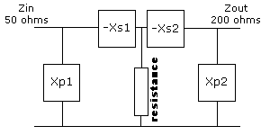
for a Zin = 50 ohms and Z out = 200 ohms

Figure 4 - bartlett's bisection theorem as applied to low pass filters
For the R/H or Load side
Xp2 = Rp / Qp = RL / Q = 200 / 3 = 66.6 ohms
Xs2 = Q * Rseries = 3 * 20 = 60 ohms
For the L/H or Source side
the Q1 here is the ratio of Rs to R or;
Q1 = SQRT [ ( Rs / R ) -1 ]
Q1 = SQRT
[ ( 50 / 20 ) -1 ]
Q1 = 1.2247 AND;
Xp1 = Rs / Q1 = 50 / 1.2247 =
40.83 ohms
Xs1 = Q1 * Rseries = 1.2247 * 20
= 24.494 ohms

Figure 5 - bartlett's bisection theorem calculations low pass filters
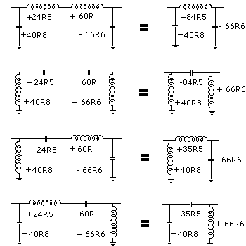
Each of the four reactances we have calculated can be either an inductor OR a capacitor. The only aspect you must remember is that the Xp's and Xs's are of opposite types or signs and add or subtract accordingly.
From this we can obtain four different networks. Everything is shown
as reactances and I have omitted source and load impedances.

Figure 6 - bartlett's bisection theorem network calculations
Notice how like reactances add. But capacitive reactances are negative and inductive reactances are positive. If the net reactance finishes negative then its a capacitor, net positive is an inductor.
The first network is obviously a low pass filter. The second becomes a high pass filter the other two exhibit high or low pass characteristics. Do you use the configuration on the left or the configuration on the right?
This will entirely depend upon individual circumstances, availability of components etc. and in particular the need to sometimes include a variable element in your circuit. Other times you may wish to include the inductor in the collector of your circuit and need a blocking capacitor to the next stage. This scenario however must take into account the effect circuit strays and transistor capacitance would have on your design and its' subsequent response.
To translate its use in the real world you simply convert your reactance at the frequency of interest. Consider the low pass filter. We have two capacitive reactances of 40.83 ohms and 10 ohms. At a cut off frequency of 7.5 Mhz they would be 520 pF and 2122 pF respectively (use 330 pF + 180 pF for 520 pf and use a 2200 pf - .0022 uF capacitor for the other). The inductor reactance of 44.5 ohms is a 0.944 uH inductor.
If this filter were in some low level application such as the 200 ohm output of an amplifier to a 50 ohm load, I'd consider making the inductor a variable to achieve improved amplifier performance by adjusting inductance while observing amplifier output into a known 50 ohm resistive load.
band pass filters
high pass filters
IF amplifier filters
harmonic trap filters
reactance
subscribe to FREE monthly newsletter
join our "electronics discussion group"
NEW! - How to link directly to this page
Want to create a page link to me from your site? It couldn't be easier. No HTML knowledge required; even the technophobes can do it. All you need to do is copy and paste, the following code. All links are greatly appreciated; I sincerely thank you for your support.
Copy and paste the following code for a text link:
and it should appear like this:
<a href="http://www.electronics-tutorials.com/filters/low-pass-filters.htm" target="_top">visit Ian Purdie VK2TIP's "LC Low Pass Filters" Page</a>
visit Ian Purdie VK2TIP's "LC Low Pass Filters" Page

This site is hosted at WebWizards.Net for better value.
Please send me your valuable comments and suggestions! Tell your friends, tell a news group, tell your favourite magazine, heck tell the world!
Absolutely essential to keeping abreast of new and updated electronics tutorials is our comments or subscribe to our highly regarded FREE monthly newsletter form. Unsubscribe any time you like. You can view immediate past issues here to see if it is to your liking.
the author Ian C. Purdie, VK2TIP of www.electronics-tutorials.com asserts the moral right to
be identified as the author of this web site and all contents herein. Copyright © 2000, all rights reserved. See copying and links.
These electronic tutorials are provided for individual private use and the author assumes no liability whatsoever for the application, use, misuse, of any of these projects or electronics tutorials that may result in the direct or indirect damage or loss that comes from these projects or tutorials. All materials are provided for free private and public use.
Commercial use prohibited without prior written permission from www.electronics-tutorials.com.
Copyright © 2000, all rights reserved. URL - http://www.electronics-tutorials.com/filters/low-pass-filters.htm
Updated 1st December, 2000
webmaster@electronics-tutorials.com