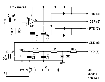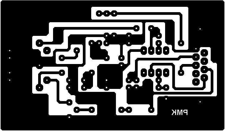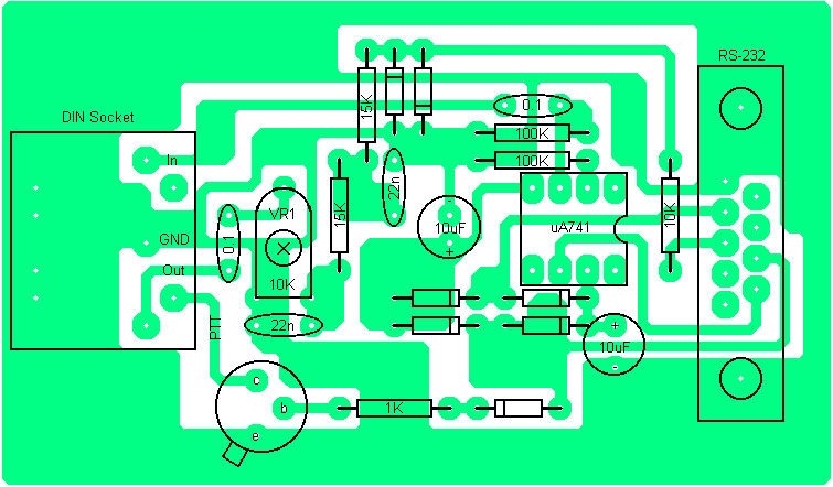

This design is made up from three parts: The receive section, the transmit section and the PTT section.
The heart of the unit (receive section) is based around a common op-amp I.C which acts as a comparator. Audio taken from your receiver is fed to the input and the output is squared before entering the computer port.
Output from the RS-232 port, pin-3 (TXD) is fed through the resistor/capacitor network before entering your transceiver. Some constructors may wish to omit the two back-to-back diodes. These tend to 'square' the wave form of audio and omitting these will give a more 'rounded' wave similar to a sine waveform.
The 10K variable resister attenuates the signal.
The PTT circuit is taken from pin-7 (RTS) and fed to the NPN transistor. When the base pin is taken "high" the collector goes "low" thus switching the PTT circuit in your rig.
No external supply is needed as the circuit is self-powered from the computer.


See the page Resizing Your Artwork for the correct printout component spacing.
Best Regards... Pete
http://www.keirle.fsnet.co.uk