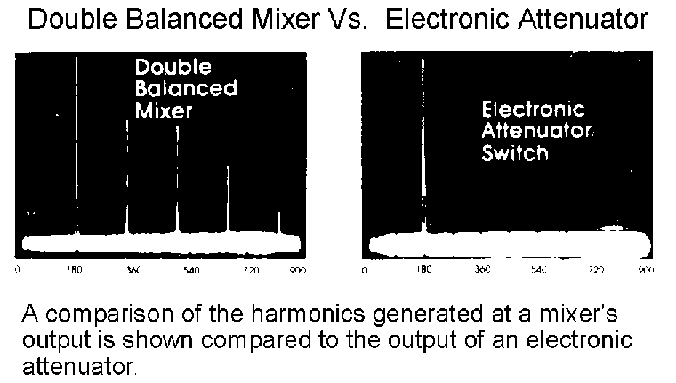
Electronic Attenuators

A useful feature of Mini-Circuits' electronic attenuators is the ability for either a positive or negative control current to provide the same amount of attenuation between input and output; this makes it useful for biphase modulation applications. The computer- automated performance data (CAPD) included for Mini-Circuits' electronic attenuators charts the phase difference between plus and minus modulation as a function of RF frequency.
The attenuator/switches are economically priced while covering the very broad frequency range from 1 to 2000 MHz. They offer low insertion loss (1.4 dB) high isolation (65 dB) and exceptional unit-to-unit matched performance.
Applications include power leveling and bi-phase modulation as well as current-controlled attenuation.

insertion loss:
must be defined at a particular value of control-current. The minimum insertion loss for Mini-Circuits' units is the difference in power from input to output with 20 mA at the control port.
in-out isolation:
insertion loss of the attenuator from input to output port when there is no current applied to the
control port.
in-control isolation:
insertion loss of an electronic attenuator measured from the RF input to control port. This
insertion loss is independent of the amount of control current and is dependent on the transformer
used to provide coupling from RF input to the internal diodes.
return loss:
the amount of reflected power at the input relative to the amount of incident power at the input
for a specified control current. At very high control current, return loss is very high; at low
control current levels, return loss is very small.
Last Updated: 12/22/1999