Most Often Asked Questions About QPSK Modulators
Q: What is the difference between a biphase modulator and a quadrature (QPSK) modulator?
A:
The biphase modulator has two phase states, 0 degree and 180 degree, modulated by
switching polarity of the dc voltage at the control ports.
The basic elements in a QPSK modulator are a pair, (each pair in quadrature to each other)
matched bi-phase modulators, modulated by switching polarities of dc voltage controls in 4
different logics for 4 phase states.
Q: How can I improve output phase accuracy in order to suit my application?
A:
The Mini-Circuits' modulators are wideband units. Tighter specs can be achieved in narrow
band. If there is a choice on operating frequency, select the lowest frequency where better phase
accuracies can more easily be achieved. Additionally, please contact our applications team about
selecting for tighter specs from our standard units.
Q: Is there a lower limit for RF input power level?
A:
QPSK modulators can be operated at low RF input power, typically 10 dB above the noise
threshold when operated at nominal saturated control current.
Q: My application requires a fast switching time. What should I look for in the phase
modulator?
A:
MCL uses Schottky-barrier diodes in QPSK modulators, which have a bandwidth greater than
500 MHZ to achieve very fast switching.
Q: The MCL catalog specifies that all data are taken at a control current +20 mA. What
changes can I expect in phase modulator performances if my control current is lower than
+20 mA? higher than +20 mA?
A:
With too low current at the control ports, the insertion loss of the modulators will be
increased due to insufficient operation. Too high current control does not help since the diodes
are already turned on. High current can also damage the diodes; typically ±5% tolerance of
control current is acceptable.
Q: What changes should I expect in performance of a 50-ohm phase modulator being used in
a 75-ohm system?
A: All phase modulators shown in the handbook are optimized for 50-ohm impedance. If your
application requires QPSK modulators operating in a 75-ohm impedance system, request test
data for the desired model from the Applications team. If you require tight tolerance
specifications, we will design a unit to meet your requirements.
I&Q Modulators and Demodulators
Q: What does I&Q mean?
A:
An RF signal can be represented in X-Y coordinates as magnitude of X & Y vectors. In
digital radio, X is replaced by I (In-phase) and Y by Q (Quadrature phase).
Q. Do I need filters at the demodulator I&Q output?
A:
Yes. Beside the desired IF signal, the sum of the LO and RF signals is also present and must
be filtered out. It is important that the filters introduce minimal group delay. Flat time delay
filters, such as Mini-Circuits PBLP series, are recommended.
Q. What is an I&Q modulator/demodulator?
A:
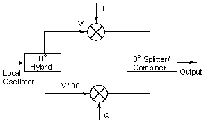
A popular form of an I&Q modulator/ demodulator consists of a 90° splitter, two mixers and a
0° combiner/splitter, as shown below.

In a modulator, the incoming data stream is split into two independent bit streams to form l&Q
signals. These are upconverted in mixers 1 & 2. Since the local oscillator signals to the mixers
are 90° apart in phase, the outputs of mixers 1 & 2 are orthogonal. These signals are vectorially
combined in a 0° hybrid. In essence, the quadrature nature of I&Q modulation is used for
bandwidth reduction of modulated signals. By proper coding, of I&Q signals an I&Q modulator
can be used for higher-order modulation. In a demodulator, the RF signal is applied to the 0°
hybrid and the output I&aQ signals are decoded.
Q. What is the difference between an I&Q and QPSK modulator?
A:
An I&Q modulator can be used as a QPSK modulator. As an I&Q modulator, mixers operate
in the linear range. In a QPSK (360° in 90° steps) modulator (such as Mini-Circuits QMC-100),
mixers behave as bi-phase modulators and operate in a saturated mode.
Q. What are the most important specs of an I&Q modulator/demodulator and why?
A:
The most important specs of an I&Q modulator are the carrier and sideband rejection. Carrier
rejection indicates the amount of the unwanted carrier present at the output. Sideband rejection
signifies the orthogonality and amplitude balance of the modulator. The higher the rejection, the
better the modulator. The carrier is an unwanted signal at the output; thus there should be as high
a rejection as the system requirement demands. For a demodulator, the most important specs are
amplitude and phase balance (deviation from 90°). These numbers indicate the degree of
orthogonality present in the demodulator.
Q. How can we improve sideband rejection?
A:
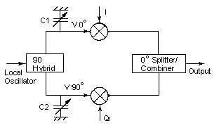
Additional sideband rejection can be achieved by adding trimmers at the output of the internal
90° hybrid, as shown below.

Cl and C2 are external components to the I&Q network and are connected across pins 9 & 12 of
Mini- Circuits' MIQC-895M. Typically, 5 to 10 dB additional rejection can be achieved. All
modulators do not have access to internal 90° hybrid. Consult factory with your specific
requirement.
Q. What limits the bandwidth of I&Q ports?
A:
Mini-Circuits' I&Q modulators use Schottky- barrier diodes and can perform well up to and
beyond the specified frequency. Beyond the specified frequency, slight degradation in
performance can be expected.
Q: Is there a difference between a modulator and demodulator at the same frequency?
A:
Not much. Mini-Circuits' modulators and demodulators are tested for the specified function to
confirm the specs. The higher the frequency, the greater the chance of a modulator not
performing as well as a demodulator.
Q. What is the advantage of buying an I&Q modulator instead of building one?
A:
Lower cost and smaller size. The I&Q modulator consists of two phase matched mixers, a 90°
power splitter and a 0° power splitter. Interface matching between these elements are essential to
maintain the phase relationships of each element. Mini-Circuits I&Q modulators are designed
and manufactured to ensure excellent repeatability of each element of the modulator. Ferrite
cores used are matched before they are wire wound as transformers. Mixers diodes are amplitude
and phase-matched. The result, excellent unit to unit repeatability without tuning. The cost
savings of this low cost manufacturing process is passed on to our customers.
Last Updated: 09/08/1999


