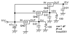
*** I live in Tsuchiura city in Ibaraki- Pref. Several years ago the only one electric parts shop in my town shut off his business. Therefore I must go to Akihabara town to get only on voltage regulator while I make a rig. Akihabara is about 2 hours from my house by train. By the way I got many , about 20 of, three terminal 5V voltage regulator from my friend. I tried to make some voltage from these regulators. Please see the figure. IC1 works as normal 5V regulator. The ground terminal of IC2 is biased with 5V made by IC1. Therefore the output voltage of IC2 becomes 10V. The ground terminal of IC3 is biased with 10V made by IC2. Therefore the output voltage of IC3 becomes 13V. This circuit needs RL1 and RL2 to make to flow the proper idle current on IC1 and IC2. And normal heat fin of regulator IC is connected to the ground terminal , so you should isolate the fin of IC2 and IC3 from the ground to bias them.
savr2.gif

3端子レギュレータを直列に使う方法の紹介
私の街(茨城県土浦市にも以前は代表的な半導体やケースを一通り扱っている、パーツ屋さんが在ったのですが、数年前(1998年頃)に店じまいしてしまい、いまや3端子レギュレータでさえ秋葉原まで行くか、通信販売で注文して送られてくるのを待たねばなりません。無線機を製作中にどうしても、電源の安定化の為に、3端子レギュレータが必要になる様な事が多く、それだけで、製作が何日間も遅れるのはこまりものです。一方、やはり数年前に、5Vの3端子レギュレータを友人から20個ほど分けてもらいましたので、これを使っていろいろな電圧に使いたいものです。ここでは、5Vのレギュレーターを複数個使って、10Vや15Vの安定化電源を製作する方法をお知らせしましょう。図をご覧ください。IC1は普通の5Vレギュレータです。IC2は、グランド端子に、先ほどIC1で作った5Vが加えられているので、10V出力となります。また、同様に、IC3は、グランド端子が10Vでバイアスされているので、出力として15Vを発生します。実を申せば、この回路は3年前にも実験してうまく行かなかった回路なのですが、IC1とIC2の出力にRLとして100オー ムを接続し、アイドル電流を適当に流す事によって今回成功しました。
back to index