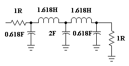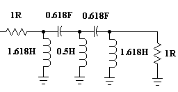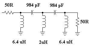
Fig 1 - low pass filters - equal teminations".
Assuming you have mastered the design of low pass LC filters we will now proceed to the design of a high pass filters. A high pass filter is simply the transformation of a low pass filter. For our purposes we will say we need a five pole butterworth filter with a cut off frequency Fc at 2000 Khz. That is we want to pass all frequencies above 2000 Khz but attenuate those below 2000 Khz.
Perhaps this might be required for the antenna input to a receiver where AM Radio interference is proving troublesome.
Let us first review the design procedure for a similar five pole filter but as a low pass filter. From our design tables we know that for equal source and loads:
|
|
|
|
|
|
|
|
|
|
|
|
|
|
|
|
|
|
|
|
|
|
|
|
|
|
|
|
|
|
|
|
|
|
|
|
|
|
|
|
|
|
|
|
|
|
|
|
|
|
|
|
|
|
|
|
|
|
|
|
|
|
|
|
|
|
|
|
|
|
|
|
The table above applies to the two low pass filters shown below in fig
1. Note the subtle differences.

Which type you choose is a matter of choice which may well be influenced
by your needs in some applications to have a DC blocking capacitor in the
input or output of the final finished high pass LC filter. In this case
use schematic 2.
In the two schematics shown in figure 1 the principal difference is
the placement of the first capacitor, denoted either C1 or C2. Depending
on the circuit configuration chosen, you read the values from the top of
the table or the bottom of the table. Is that clear? Also I have only presented
one table, there are hundreds of tables and filter types with varying responses
but Butterworth is fairly easy to compute. We said earlier we would use
a five pole filter and we will opt for the top type of filter so we should
have these values.

Notice that this low pass filter is normalized to 1 ohm impedance both in and out, a frequency of 1 Hz and capacitor values are expressed in Farads while Inductor values are in Henries.
All right we have a low pass filter prototype, what now? We simply want to do the opposite to a low pass with our high pass filter, so we do the opposite and invert everything. Replace each component with it's opposite.
A capacitor becomes an inductor and, an inductor becomes a capacitor
and, at the same time the values are also inverted e.g. the first capacitor
of 0.618F becomes an inductor of 1 / 0.618H. Cool?

Notice that in the schematic I have already done the reciprocal or the inversion. The first capacitor was 0.618F, converting to an inductor of 1 / 0.618 becomes 1.618H (check it out on the calculator for ALL the components). Now all we have to do is get back to a standard impedance, we'll use 50 ohms but it could be any value which is suitable to our requirements. Also we need to get back to our cut off frequency of 2000 Khz.
This is the truly simple part if you like doing basic sums on the calculator. If not, then you're in for some bother.
The transformation is effected using the following basic, yet simple
formulas:

Here C is the final capacitor value, L is the final inductor value, Cn and Ln are the prototype element values in Fig 3, R is your final impedance value and fc is the final cut off frequency. It's as simple as that!
So for a cut off of 2000 kHz and a 50 ohms impedance the calculations
for the first capacitor and inductor we encounter become, as a worked example
for you.

Note that the original prototype is always expressed in terms of 1 ohm, 1 hertz (Hz), Farads and Henries.
When you do your sums you get back to numbers with negative exponents, they are the -10 and the -6 respectively. To bring capacitance to pF we multiply by exponent 12 (that's number 1 followed by 12 zeroes as in 1,000,000,000,000). Why? because 1 Pf is one 1,000,000,000,000th of a Farad.
To bring inductance to uH we multiply by exponent 6 (that's number 1 followed by 6 zeroes as in 1,000,000). Why? because 1 uH is one 1,000,000th of a Henry.
Your final filter comes out as follows:

Let's look again at our previous oscillator circuit. If you are unfamiliar with oscillators then review my previous oscillator tutorial. It will certainly help you.
Firstly don't use an unnecessary precision with your values. A capacitance calculated as 983.5752483 pF is totally irrelevant. In the "real world we would use a standard 1000 pF capacitor, remembering it's tolerance is going to be +/- 5% anyway. Consider also, it is doubtful any impedance will be precisely 50 ohms. Finally, for this type of filter toroids are ideal to use as inductors.
If their is sufficient interest I'll cover designing for unequal impedance
terminations.
the author Ian C. Purdie asserts the moral right to be identified as the author of this web site and all contents herein. All rights reserved. See copying and links. These electronic projects are provided for individual private use and the author assumes no liability whatsoever for the application, use, misuse, of these projects that result in the direct or indirect damage or loss that comes from these projects. All materials are provided for free private and public use. Commercial use prohibited without prior written permission from Ian C. Purdie.
| Revised 28th July, 2000 | My privacy statement | Subscribe to my FREE monthly Newsletter | |
| Email to: Ian C. Purdie | URL: www.integritynet.com.au/~purdic/high-pass-filters.htm | Copyright © 1998-1999-2000 by Ian C. Purdie | |