COMPLEX BANDPASS FILTERS - part 1
Now we move from the simple to the complicated. By this stage you should be able to understand:
unloaded Q ( QU )
loaded Q ( QL )
reactance
LC circuit combination for any given frequency
Bandpass filters are derived from tables named after the mathematicians who did the original calculations.
The main filters considered are:
Butterworth
Chebyschev
Bessel
Gaussian
Because of ease of alignment we will consider only the two and three resonator Butterworth bandpass filters of the narrow band variety. Here the term narrow band is a relative expression. Do NOT expect to design such a filter at 9 Mhz with a bandwidth of 3 Khz.
A generalised statement:
"A competent qualified design engineer, with a wealth of experience may design, construct and align an LC filter of about 1% bandwidth".
This would mean at 10 Mhz an excellent filter would have a bandwidth of 100 Khz.
The following filter calculations may be depicted in other publications in another format but you will essentially arrive at the same answer. Although here we will only consider two and three resonator stages I have presented data for up to 5 stages. This is for the benefit of the keener constructor.
Also remember that adding further stages only improves your shape factor. This of course may well be your design goal and that is quite fine however, you do pay the price of increased insertion loss for adding stages.
In a normal professional design situation a designer would consult other tables to determine the number of stages required to achieve a given shape factor.
BUTTERWORTH - Capacitively coupled resonators
|
|
|
|
|
|
|
|
|
|
|
|
|
|||
|
|
|
|
|
|
||
|
|
|
|
|
|
|
|
|
|
|
|
|
|
|
|
Step 1 - determine your design goal:
I know that sounds pretty basic but you would be surprised just how often that aspect is overlooked.
In our case we are going to design and construct a front end filter for a receiver which operates between 7.0 and 7.2 Mhz. Our receiver has an I.F. of 9.0 Mhz and therefore our local oscillator operates from 16.0 Mhz to 16.2 Mhz. The nearest image frequency would be 25.0 Mhz. This is a ratio of 25/7 or 3.57:1 (for the purists that is 3.57 radians/second).
Other tables would tell us that an n = 3 resonators Butterworth filter will give us an attenuation of about 32db to 25 Mhz.
Step 2 - determine your centre frquency:
I will be a little pedantic here and introduce, for the purpose of this exercise the expression "geometric centre frequency". This is simply the square root of ( F1 * F2 ) which calculates to 7.0993 Mhz. Although only fractionally different from what one would assume to be the centre frequency i.e. ( F1 + F2 ) / 2 or 7.1 Mhz the frequency of 7.0993 is the correct centre frequency or Fo.
Step 3 - determine your bandpass Q or QBP:
Bandpass Q is Fo/Bw or 7099.3/200 which equals 35.5
Step 4 - denormalise your table q and k parameters:
From the table above take q1 and qn and multiply by Qbp this will give you respectively values of 35.5 and 35.5 (thrilling mathematics here).
Again from the table above take k12 and k23 and this time divide by Qbp this will give you respectively values of 0.02 and 0.02 (again thrilling mathematics here).
Step 5 - do NOT yet select an appropriate inductor :
Because this type of filter is based on narrow band approximations and the k and q values assume infinite inductor Q, the inductor you select must have an unloaded Q at least several times higher than the design Q. Here we would look for a QU of at least 140. Obviously any inductor you select which meets this criteria would be suitable BUT jumping ahead quite a bit in our calculations we find we need practical values for coupling capacitors. e.g. at least 2p2.
Step 6 - select a practical value of coupling capacitor:
*** You definitely won't find this sly but cunning step in the design books ***
Now we all know about L/C. For our Fo of 7.0993 we need an LC of about 503. With this type of filter LC is calculated as [ ( 25330.3 ) / ( F1 * F2 ) ]. Nifty!.
Assume a coupling capacitor of 3p9:
From step 4 above K12 = K23 = .02 and normally the coupling capacitor is determined by K12 * Co where Co is the resonating capacitor. Or C12 = K12 * Co
So if we want Co to be 3p9 then Co must be C12 / K12 or 3p9/.02 or 195 pF.
Why do all this????. O.K., assume you had picked an inductor of 10 uH. The resonating capacitor Co must be 503 / 10 or 50.3 pf AND C12 would be .02 * 50.3 pf which is 1 pF. I know they exist but I don't like very low values and in some designs it is not uncommon to find an answer of 0.25 pF. That's why!!!.
Step 7 - select an appropriate inductor now:
With a Co of 195 pf our L must be 503 / 195 or 2.58 uH, an eminently practical and achievable value with probable HIGH Q. Later you will see our design impedance is also reduced as a result.
What about our resonating capacitor?. There are no 195 pF capacitors!. First off the actual value you use must be Co - C12 - C34 which then brings you back to 187 pf. It is highly unlikely your inductor will equal exactly 2.58 uH and there is stray circuit capacitance everywhere. In the real world we would use a standard 150 pF capacitor in parallel with a 40 pF trimmer so we can tune our filter.
A suitable inductor of about 2.58 uH would be an Amidon T 50-6 toroid wound with 25t of # 22 wire. Incidentally the Q of this inductor would be about 255 at the frequency of interest (see Amidon data book).
Step 8 - determine the filter theoretical impedance now:
Dead easy, its simply from step 4
the denormalised q1 and
qn's
* XL
Which in our case is 35.5 * 115 = 4K082
If that makes no sense then either you haven't been paying attention or you short circuited the tutorial (now go back to the basics).
Step 9 - connecting to the real world:
Here is the important stuff. Our filter must be properly terminated to work as expected.
Assume our source is from a proper 40 metre antenna of 50 ohms impedance and our load is a gee-whiz-bang-all-singing-all-dancing passive double balanced mixer which also needs to see 50 ohms.
You have two options.
(a) transformer coupling i.e. 4082:50 which is a turns ratio of about 9:1 (check it out) leaving us with something like an impractical 2.7 turns coupling.
(b) capacitive coupling again. Where Cc is calculated by calculating reactances:
where XCC=
or in our example XCC =
which of course equals 449 ohms and at 7.0993 Mhz = 50 pF
This 50 pF is then subtracted from both Co's at either end to reduce that capacitance from 150 pF to 100 pF.
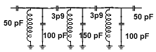
NOTE: I have not depicted the 3 variable trimmers in parallel, in this schematic
And that's all folks for this type of basic filter. Next I will move on to more complicated types including the old IF Amplifier type.
the author Ian C. Purdie asserts the moral right to be identified as the author of this web site and all contents herein. All rights reserved. See copying and links. These electronic projects are provided for individual private use and the author assumes no liability whatsoever for the application, use, misuse, of these projects that result in the direct or indirect damage or loss that comes from these projects. All materials are provided for free private and public use. Commercial use prohibited without prior written permission from Ian C. Purdie.
| Revised 12th March, 2000 | My privacy statement | Subscribe to my FREE monthly Newsletter | |
| Email to: Ian C. Purdie | URL: www.integritynet.com.au/~purdic/complx_bpf.html | Copyright © 1998-1999-2000 by Ian C. Purdie | |