Low-cost Ultra High Isolation SPDT Switch
Introduction
Wide-band test instrumentation often needs signal routing. This is accomplished with mechanical switches, which are expensive and slow. When isolation requirements are not high, it is also done with electronic switches. Some high isolation switches available in the market are very expensive. Mini-Circuits has developed a pair of low-cost, high isolation, fast switching, TTL-driven, connectorized-switches that have a typical isolation of 85 dB at 1 GHz and 60 dB at 5 GHz. Two versions, absorptive and reflective have been introduced. This paper will describe these DC-5 GHz high isolation switches and a typical application.
Fig. 1
Performance
Signal routing and automated testing are two major applications of switches. Mechanical switches have high isolation and low-insertion loss. However, they have very long switching time and limited life. Solid state switches using GaAs FETs overcome these problems and are extremely popular in switching applications. They have many advantages such as small size, extremely fast switching, low cost and long life. When these switches are integrated with TTL drivers, they can be easily driven with other logic circuits or with a personal computer having TTL driver cards.
The main disadvantage of the GaAs switch is the moderate isolation. Circuit designers need to cascade the switches and integrate the driver, which consumes large amount of board space. In order to solve this problem, Mini-Circuits introduced a pair of solid state, high Isolation switches1 with integral driver. These switches - ASW-2-50DR (reflective) and ASWA-2-50DR (absorptive) - provide an isolation of 53dB typ. at 1 GHz and 35dB at 5GHz. A reflective switch provides a short circuit termination at the output "off" port and an absorptive switch provides a 50-ohm termination at the same port. Choice of the switch depends on the application.
For applications requiring even higher isolation, a pair of switches ZASW-2-50DR (reflective) and ZASWA-2-50DR (absorptive) have been introduced. These were developed by cascading the ASW-2-50DR and ASWA-2-50DR switches. Careful layout and internal shielding was done to preserve the isolations.
Figure 1 shows a photograph of the unit and Table-I contains their specifications.
ZASW series switches have extremely high isolation. The isolation is typically 100 dB to 100 MHz, 90 dB to 1 GHz, 80 dB to 2GHz and 60 dB to 5 GHz. These high isolations can minimize the leakage from the unselected port to an extremely low level. Figure 2 shows the isolation of the reflective and absorptive switch.
These building block switches are solid state and hence have extremely fast rise and fall times, 5 nsec typ. and switching time of 10 nsec typ. This is extremely useful in automated test environments. For example, typical test times vary from few msec to few seconds and ZASW switches have only a few nanosec switching time. Hence, the overhead added by these switches is very low.
Although this is a cascade of several switches, the insertion loss of these switches is moderate and is typically, 1.8 dB to 2 GHz and 3 dB at 5 GHz. Figures 3 shows the insertion loss of the reflective and absorptive switches. Fig. 4 shows the VSWR of the absorptive and fig.5 that of the reflective switch. Note the VSWR of the reflective switch output port in off state is high.
A typical Application
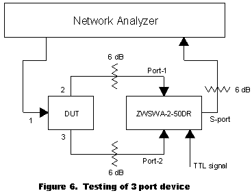
Figure 6 shows the use of the absorptive (ZASWA-2-50DR) switch in a low-cost, high accuracy, automated test application. It consists of a vector network analyzer, such as the HP8753E, device under test (DUT), attenuators and the high isolation switch. The attenuators are added at all ports of the switch to improve the return loss. For this purpose, the return loss of the attenuators should be extremely good and we chose Mini-circuits precision 6-dB attenuator, BW-S6W2. Initially, the analyzer is calibrated by connecting the cable going to port 1 of the DUT to port 1 of the switch. At this time the switch is turned on to provide low-insertion loss from S-port to port-1. This state of calibration (state-1) is saved in an instrument register. Then the calibration is repeated with cable going to port 1 of the DUT connected to the port 2 and the switch. At this time, the switch is in "on" position from s-port to port-2 and the cal data is saved in a different register (state-2). Now the DUT is connected as in Fig 6. By keeping the switch in an on state from S to port 1and recalling the cal state-1, insertion loss of the DUT from port-1 to port-2 can be measured. Similarly, by turning the switch on from S to port-2 and recalling the cal state-2, the insertion loss of the DUT from port-1 to port-3 can be measured. It is also possible to measure the return loss at the port-1 of the DUT in any of the above switch states and that of ports 2 & 3 when the insertion loss from 1-2 and 2-3 respectively are measured. By connecting a personal computer, these measurements can be automated.
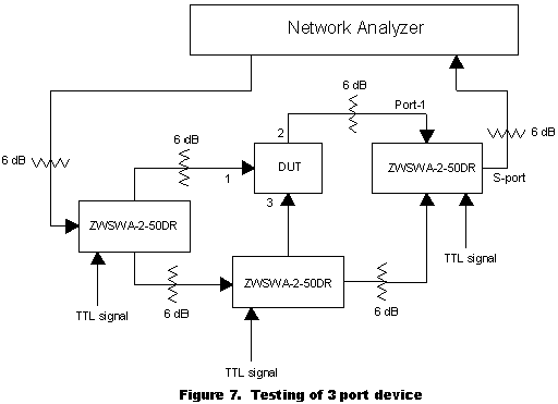
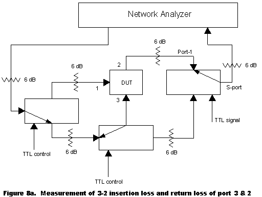
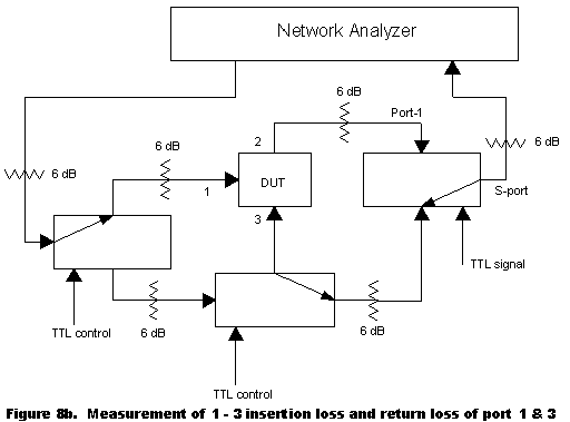
The disadvantage of the above set up is that only two of the possible three insertion loss states can be measured. By using three switches instead of one, this disadvantage can be overcome. Figure 7 shows the connections with three switches. Figures 8a to 8b show the state of the switches for various measurements. For non-reciprocal devices, the insertion loss states can be twice as many. By using a network analyzer with two port S-parameter set and using the set up in fig 7, all these states can be measured by interchanging the stimulus and response states of the analyzer.
Conclusion
A pair of high isolation switches has been introduced. These switches cover most of the frequency bands of commercial, high volume markets. They can be used with a personal computer to produce a low-cost, high speed, automated test station. They can also find application in signal routing in communication equipment.
Reference
1. High Isolation Switches, pp. 164-168, Microwave Journal, September 1998


