Most Often Asked Questions
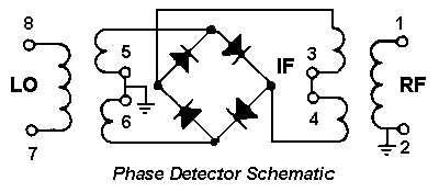
Q. Can you explain, briefly, how a DBM works as a phase detector?
A.
When a DBM is used as a phase detector, this is merely a special case of mixing action where the LO and RF signals are at the same frequency. Now, let's look at the mixer equation:IF output = A1 cos[(![]() -
- ![]() )t - (ØLO - ØRF)]
)t - (ØLO - ØRF)]
+ A2 COS[( ![]() -
- ![]() )t - (ØLO - ØRF)]
)t - (ØLO - ØRF)]
+ [higher order frequency terms]
In a phase detector application, ![]() =
= ![]() ; therefore in the first term,
; therefore in the first term, ![]() -
- ![]() = 0 and thus
the IF output is only a function Of A1 COS(ØRF - ØLO) + A2 cos (2
= 0 and thus
the IF output is only a function Of A1 COS(ØRF - ØLO) + A2 cos (2 ![]() t) + higher frequency
terms. With proper filtering, the 2
t) + higher frequency
terms. With proper filtering, the 2 ![]() t terms and higher can be eliminated so the IF output is
equal to Al COS(ØRF -ØLO).
t terms and higher can be eliminated so the IF output is
equal to Al COS(ØRF -ØLO).
Specifications of a DBM that are important in a phase detector application include:
(1) DC offset,
(2) maximum DC output,
(3) isolation between ports,
(4) polarity of output voltage,
(5) frequency response,
(6) temperature variation of DC offset.
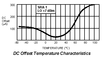
Q. How is DC offset affected by temperature?
A.
The value of the DC offset varies with temperature. Over a wide temperature range, say from -55 to + 100o C, the unbalance of the mixer diodes will have a major influence on the DC offset with only a slight contribution from the transformer.
An effective technique to minimize DC offset variation with temperature is to use diodes whose characteristics track with temperature. This can be accomplished by using diodes manufactured from the same wafer In the same production lot. At Mini Circuits, this selection technique is used exclusively in the production of mixers. Also Mini-Circuits employs specially-designed winding machines so that the assembled transformers have well-matched windings.
The net result-Mini-Circuits offers ultra-low DC offset characteristics; less than 300 to 400 ![]() V
over a -55 to 100o C temperature range.0
V
over a -55 to 100o C temperature range.0

Q. Why is DC offset so important?
A.
Q. Suppose the DC output of a DBM phase detector is insufficient for my application. What do
you suggest?
A.
Q. I want to compare the phase of two square waves. Do I have to convert them to sine waves
before applying them to a phase detector?
A.
Q. Is there any difference in the frequency range spec when a DBM is used as a phase
detector?
A.
Q. Isolation specs for LO to RF and LO to IF are generally included in mixer specs, but RF
to IF isolation is often not listed. What are typical values?
A
Q. I intend to use an op amp following the phase detector. What potential problems do I face?
A.
A solution to remedy these problems involves a simple RC filter as shown. Since the op amp has
a very high input impedance. The 1K series resistor does not attenuate the DC output from the
phase detector. Also any small DC voltage at the op amp is attenuated by 20:01 (by the 1K and
51-ohm resistor combination) at the phase detector output. The RC combination acts as a low pass-filter to attenuate the sum frequencies; if
additional filtering is required, a multiple-section RC filter can be used.

Q. Is it necessary to provide a filter at the output of the phase detector?
A. In many cases, yes, the RF1 and RF2 term (w1 + w2,) must be removed since it may cause system degradation. The frequency terms in the IF output can leak into the system and cause amplifier saturation or other seemingly unexplained results.
Q. What are the basic steps to select the proper phase detector?
A.
Finally, if phase accuracy is critical, specify the maximum DC offset tolerable for the intended frequency range and, at your request, Mini-Circuits will test and screen to insure this requirement is met at minimal or no charge.
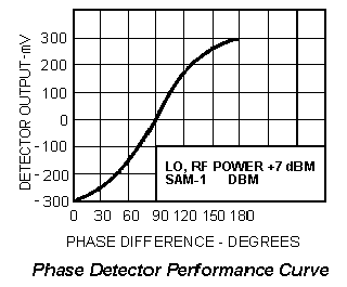
Q. What is the performance characteristic of a phase detector?
A.
Q. Is the DC polarity output of a phase detector fixed by the manufacturer or can the polarity
be reverse at the user's discretion?
A.