|
I am no longer maintaining the electronics sections of this site. For an explanation, see the electronics contact page. |
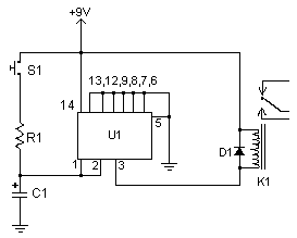
Parts:
| C1 | 1 | See Notes | |
| R1 | 1 | See Notes | |
| D1 | 1 | 1N914 Diode | |
| U1 | 1 | 4011 CMOS NAND Gate IC | |
| K1 | 1 | 6V Relay | |
| S1 | 1 | Normally Open Push Button Switch | |
| MISC | 1 | Board, Wire, Socket For U1 |
1. Email jawaharlal@excite.com with comments, questions, etc.
2. To calculate the time delay, use the equation R1 * C1 * 0.85=T, where R1 is the value of R1 in Ohms, C1 is the value of C1 in uF, and T is the time delay in seconds.
3. S1 may be replaced with an NPN transistor so the circuit can be triggered by a computer, other circuits, etc.
4. Most any 6V relay will work for K1. If you use a large relay, you my need to add a transistor to the output of the circuit in order to drive the larger load.