
I built a small version of this and it works great. The above circuit drawing is the next Marx Generator I am going to build. C1 on the left and C2 of the right are both #24 wire close wound on a 1" PVC pipe 12" long. The capacitors are all door knobs 570 pf 40KVDC. I stood the 2 coils up like 2 Tesla Coil secondaries. The 2 coils are 3" apart. I soldered the capacitors to the side of each coil 1 1/2" apart. The solder joint will short out about 3 or 4 turns of wire on the coil but that won't matter. The capacitors are soldered between the 2 coils. All the capacitors are in parallel across the coils. Next I made several spark gaps .100 each and 1 gaps is .095. Spark gap #1 is the first gap at the bottom and it is .095. The spark gaps are soldered to the capacitors to make them all be connected in series. I used a 20 KVDC power supply in my test. The power supply charges up all the capacitors because they are all in parallel. When the voltage get high enough to arc across the .095 gap voltage across gap #2 is doubles and it arcs next. Then gap 3 arcs and 4 & 5 and so on until all the gaps have fired. This all happens in a micro second and the gaps all apear to fire at the same time. When all the spark gap fire it makes the capacitors all be connected in series. The sudden serge of power causes the coil to be high resistance. The result is a very large spark from the toroid. The power supply recharges the capacitors and the spark gaps fire again and the toroid sparks again. The cycle repeats so fast the sparks from the toroid apear to be almost continious about like sparks from a Tesla Coil toroid. I only used 6 capacitors on this test. I have 30 door knob capacitors I plan to use on the final project. I want 33,936. VDC on the power supply. The 2 coils will be 40" tall. Output voltage should be about 1,018,080. volts. The uf value of the circuit capacitors determine the current discharged to the toroid. The power rating of the power supply determines how fast the circuit recharges after a discharge. The toroid charges up like the sphere of a Van De Graff generator producing a very long and powerful spark.
=======================================================
High Voltage Power Supply #1

The tubes are 1B3GT. Both transformers are 12K 30 ma neons. The tube heaters are powered by a D size flashlight battery 1 battery for each tube. Output voltage will be 24,000. x 1.414 = 33,936.. VDC.
=======================================================
High Voltage Power Supply #2

Where the PRV rating of a single diode is not suffieient for the application, similar diodes may be used in series. (Two 500-PRV diodes in series will withstand 1000 PRV, and so on).When this is done, resistor and a capacitor should be placed across each diode in the string to equalize the PRV drops and to guard against transient voltage spikes. Even though the diodes are of the same type and have the same PRV rating, they may have widely different back resistances whenthey are cut off. The reverse voltage divides according to Ohm's Law, and the diode with the higher back resistancewill have the higher voltage developed across it. The diode may break down.
If we put a swamping resistor across each diode, the resultant resistance across each diode will be almost the same, and the back voltage will divide almost equally. A good rule of thumb for resistor size is to Multipy the PRV rating of the diode by 500 ohms. For example, a 500-PRV diode should be shunted by 500 x 500, or 250,000. ohms.
The shift from forward condition to high back resistance does not take place instantly in a silicon diode. Some diodes take longer than others to develop high back resistance. To protect the "fast" diodes in a series string until all the diodes are properly cut off, a .01 uf capacitor should be placed across each diode. The capacitors should be noninductive, ceramic disk, for example, and should be well matched. Use 10% tolerance capacitors if possible.
If T1 and T2 in the above circuit are both 15,000. volt 30 ma neons. Output voltage will be 30,000. x 1.414 = 42,420. volts DC.
If T1 is 15K and T2 is 12K the output voltage will be 38,178. volts DC.
If T1 and T2 are both 12K the output voltage will be 33,936. volts DC.
33,936. volts is probably a save voltage for the 40,000. volt door knob capacitors in the Marx Generator.
1N4007 diodes are rated 1000 PRV 1 amp.
=======================================================
High Voltage Multiplier

This is the same circuit that is used in a stun gun. All diodes are 1N4007 and all caps are .01 uf 1000 VDC. T1 is 120 VAC input and 650 VAC output. The DC voltage across the 1st cap is 919 volts. With 10 caps in series the output voltage will be about 919 x 10 = 9190 volts. I found out the hard way that if the capacitors are larger than .01 uf the diodes will all explode when the circuit is discharged. Output is between ground and the toriod.
=======================================================
This capacitor bank is 30 capacitors connected in series parallel. See the voltage multipier circuit below. There are 2 rows of 15 caps per rod. Each row of 15 caps are connected in series. The 2 rows are side by side and connected together with 1N4007 diodes zig zag back and forth between the rows of capacitors. Each diode has a 1 amp current limiting resistor in series with it. The capacitors are rated 22,000. mfd 250 VDC. I have an electrical cord connected across the input of the 2 rows capacitors. The output is in series with both rows of capacitors. When I plug it in the caps charge up in parallel and it discharges in series. The 2 rows discharge together in parallel. The output voltage is 1.414 x 120 VAC x 15 capacitors = 2545 VDC. I don't know the output current but it sounds like an explosion when it discharges. It makes a zenon flash tube flash like a small atomic blast.
This capacitor bank is 3 caps in parallel. Each cap is 210 mfd 5000 VDC 18,000. amps high energy storage capacitors. I connect a 1/8" x 36" long solid steel wire to each output terminal. The 2 wires are bent in a large circle arc with the ends coming together to make a spark gap 1/2" wide. I plug in the power supply to 120 VAC. The power supply draws so much current it makes the lights get dim in the shop as the caps charge up. After about 20 seconds the lights in the shop start to get bright again and I know the caps are almost fully charge. About 1 second after the lights get bright the capacitors discharge through the spark gap. The 2 steel wires are vaporized. The flash is about like 200 arc welders all arcing at the same time. The arc sounds like a very loud explosion much louder than the sound of a high powered rifle. This thing is dangerous. I always set this up outside in the drive way and use a 50' long extension cord to plug it in. I connected a very large flash lamp to this power supply. The flash lamp came from the airport and was used but still worked. I don't know the power rating of the flash but it was several 1000 watts. When the power supply discharged through the flash lamp it was vaporized without a trace. It made a huge flash.
I have read a capacitor bank can be discharged into a cup of water to produce a very loud and powerful explosion. The discharge vaporizes the water into instant steam. The water expands 1600 times it original volume. I have not tried this yet but I have talked to people that have and it works. I saw this demonstrated on the Discovery channel.
=======================================================
Power Light Beam

This device was invented for the Military during WWII. A huge high voltage capacitor bank is connected to the 2 carbon rods. The carbon rods make a spark gap inside a mirrored tube. The tube has a full mirror at the back end and 2 lens at the other end. The lens are flat on one side and round like a ball on the other side. The spark gap is wide enough to make the power supply charge up to 98% then discharge by itself across the carbon spark gap. The discharge produces an extremely bright white light with extreme heat like the SUN. The lens direct all the light and power in a straight line like a laser beam. The light beam can instantly burn a hole in just about anything.
=======================================================

T1 in this circuit is 8 ohms to1200 ohms audio transformer. I replaced T1 with a 120 VAC primary 600 VAC secondary transformer. Its a lot easier to build and makes lots of long continious sparks. Caps are .01 uf 1000 VDC. Diodes are 1N4007.
=======================================================
This circuit can be used on a car ignition coil or a TV flyback. The frequency is adjustable from 143 Hz to 7300 Hz for best output spark. I get a very hot blue multi spark about 3/4" long using an ignition coil.. I use this circuit for my plasma globe made from a 4" clear glass light bulb.

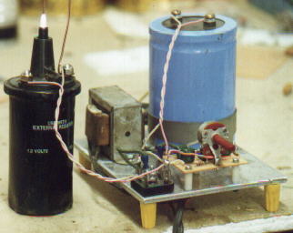
The 3/16" thick aluminum plate is 5" x 6". The aluminum plate is the heat sink for the 2N3055 transistor which is mounted in the middle. I tried a small heat sink and it over heated in about one minute. Every thing is mounted to the aluminum plate except the ignition coil. Yellow wire nuts make good legs and can be glued on or screwed onto 6-32 by 1" screws mounted through the aluminum plate. The variable resistor adjusts the frequency of the 555 timer. The transformer is 10 volts 2 amps. A 10 volt transformer will give 14.1 VDC. Maximum voltage on the 555 timers is 15 volts. The blue capacitor in the pic is 51000. uf 50 VDC. Diodes D1 and D2 makes the charge and discharge paths independently controlled and gives wide control over the duty cycle and produces an almost perfect square wave output.. Diodes D3 and D4 changes the square wave output of the 555 timer to a saw tooth output. The 2N3055 transistor is not a good choice for this high frequency circuit but it works. I used a 2N3055 transistor but an FET transistor will work much better and not get hot. The spark on the ignition coil is about 5/8" long. A 6" round clear glass light bulb on the HV terminal of the ignition coil makes a good Plasma Globe. Adjust the variable resistor to get best output on the 6" light bulb. Certain frequencies produce longer sparks for some reason. Try a 4" and 2" clear glass light bult too. This project also makes a tiny Jacobs Ladder.
=======================================================.

I have 30 capacitors connected in parallel. The caps are all 7400 MFD 200 VDC. I made things simple by using a 1N4007 diode to charge the caps and soldering a wire to the diode and plugging it directly into the 120 VAC wall outlet. I have a current limiting resistor between the diode and the caps. The caps all charge up. I unplug the wire from the wall. Close switch S1 and discharge the caps through the #36 copper wire. It looks like lighting. My wooden board is 4 feet long. My wire is 40" long. I connected a volt meter to the cap bank and it reads 161 VDC. After dicharging the caps through a #36 wire the voltage dropped to 156 volts. I was able to discharge the caps through a wire several times before it had to be recharged. I tried it again using #28 wire and the wire turned white hot and melted. This might work better with all the caps connected in series.