CMOS Digital Image Sensors

    Adding vision to your projects needs not be a difficult task. Whether its machine vision for robot control or the sampling and storage of images for security, CMOS images sensors can offer many advantages over traditional CCD sensors. Just some of the technical advantages of CMOS sensors are,

    • No Blooming
    • Low power consumption. Ideal for battery operated devices
    • Direct digital Output (Incorporates ADC and associated circuitry)
    • Small size and little support circuitry. Often just a crystal and some decoupling is all that is needed.
    • Simple to design with.

    There are many manufacturers making CMOS Image Sensors. Just some of the more notable ones are Photobit, OmniVision, Agilent (formally known as HP), ST who acquired VLSI Vision and Mitsubishi.

    There are two different categories of CMOS Sensors based on their output. One type will have a analog signal out encoded in a video format such as PAL, NTSC, S-Video etc which are designed for camera on a chip applications. With these devices you simply supply power and feed the output straight into you AV Equipment. Others will have a digital out, typically a 4/8 or 16 bit data bus. These 'digital' sensors simplify designs, where once a traditional 'analog' camera was feed into a video capture card for conversion to digital. Today, digital data can be pulled straight from the sensor.

    The main components to a Digital Video Camera design are

    • CMOS Image Sensor. The heart of the camera. It produces a digital/analog output representing each pixel. It's support circuitry will normally include a Crystal Oscillator and power supply decoupling. Some sensors may need a resistive bias network of some type. All of these components are normally surface mounted on the back of the PCB and occupies very little real estate.
    • The lens Holder. This will be either a plastic or metal mount which attaches to your PCB and allows a standard size lens to be screwed in. The screw thread facilitates focusing for fixed lens systems. The base of the lens mount may also have a IR (Infra Red) filter.
    • The Lens. This will determine your Field of view among other things. Lenses range from fish-eye to telescopic and need to be purchased to fit the parameters of your sensor and lens holder.

    Once you have completed the above, you have yourself a imaging system which constantly spits out a pixel data stream synchronised to a pixel, frame and/or line clocks. Connecting this directly to a microcontroller/processor system will cause headaches. Trying to clock this raw data in will use up great amounts of CPU time, if your uC could do it in the first place. If you drop a pixel because an ISR is doing some thing more privileged, then you have no ability to sample that location again, and thus no method of error correction.

    While the frame rate on many devices can be slowed down by using internal divisors, it still doesn't reach an acceptable speed nor allow random access to pixels. Reducing the master clock rate of the device will effect exposure times and other time dependent settings, thus is not an option. Clearly some additional circuitry will need to be designed.

    By using a CPLD/FPGA and RAM, you can program the CPLD to dump the data straight into RAM. Your micro could then read this RAM through the PLD which could be memory mapped. If you really want performance (And budget is not a problem), you could use Dual Port RAM. If however you only want to capture one frame, then the PLD could copy one frame into memory and ignore subsequent pixel data until an event such as when your device has read all the data out of RAM. Other options are to use a LVDS (Low Voltage Differential Signalling) serial bus, to relay your data over a few metres or more. At a high enough clock rate, you won't wait all day for a frame.

    The other thing you must not forget is how to control the sensor. Most of it's internal parameters are controlled by a serial bus, typically I2C for the majority of sensors. This can either be controlled through a memory mapped Register programmed into your PLD or via an I2C port straight from your uC. All up this makes quite a cheap way to capture video. Ideal for your Embedded Linux Systems.


    Photobit Corporation

      Photobit have many CMOS Image Sensors. CMOS APS (CMOS active pixel sensor) was first created by a team of JPL engineers lead by Dr Eric Fossum. Dr Fossum is now the Chief Scientist and Chairman of Photobit. Two of Photobit’s more common sensors are the PB-100 and PB-300. Other sizes can be sought from Photobit's Product Matrix

        PB-100

        • CIF Resolution - 360 x 304 Colour or Monochrome
        • 1/5 Inch Optical Format
        • 0-39 Frames a Second, 6 Megabyte Data Rate
        • Output 8 Bit Serial Digital Video, I2C Control
        • 3.3V Supply, 30mA (100mW)
        • 28-pin CLCC

        PB-300

        • VGA Resolution - 640 x 487 Colour or Monochrome
        • 1/3 Inch Optical Format
        • 0-39 Frames a Second, 24 Megabyte Data Rate
        • Output 8 Bit Digital Video Data Bus, I2C Control
        • 5V Supply, 60mA (<300mW)
        • 44-pin CLCC

    OmniVision Technologies

      OmniVision not only develops CMOS Image Sensors, but also support circuitry such as the OV-511 Advanced Camera to USB Bridge. OmniVision is one of the more popular manufacturers with devices such as the OV7910 NTSC/PAL Camera on a Chip being used in many small analog camera modules around the world. This would be the recommended starting point if you are starting out designing with CMOS Image Sensors.

        OV6620

        • 352 x 488 Colour(OV6620) or Monochrome(OV6120)
        • 1/3 Inch Optical Format
        • 0-39 Frames a Second, 24 Megabyte Data Rate
        • Output 8 Bit Digital Video Data Bus, I2C Control
        • 5V Supply, 60mA (<300mW)
        • 44-pin CLCC

        OV7620

        • 664 x 492 Colour (OV7620) or Monochrome(OV7110)
        • 1/3 Inch Optical Format
        • 0.5- 30 Frames per Second
        • Output , I2C Control
        • 5V Supply <120mW
        • 48-pin LCC

      OmniVision and some third part vendors have evaluation modules for the OmniVision sensors. This allows you to get up to speed with the sensor, incorporating a PCB with de-coupling, a Lens and Lens Holder. The majority of the sensor's signals are broken out to a header which you can use to interface to your own designs. The evaluation modules in small quantities are normally much easier to obtain than the sensors themselves, and are typically cheaper as a result.


      A picture of the M3188 Evaluation Module with
      the lens holder removed. The signals can be obtained
      from the 32 pin header on the top of the module

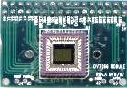
      DIY Electronics (http://www.kitsrus.com) are just one outlet which sells the third party evaluation boards.


    Mitsubishi Chips

      Mitsubishi have broken the pack, to produce smaller resolution sensors. These sensors can typically be used for a range of applications such as finger print sensing, motor detection, gaming, tracing of moving parts etc. Just one application is the new optical mice flooding the market place. They use a low resolution Image Sensor to track movement on a wide variety of surfaces.

      Also unique to these sensors is in-built image processing. Both sensors can output edge enhanced or extracted data, making them ideal for tracking on small robots, industrial control etc. The sensors can also process 2D images into 1D. The output of each pixel is by the means of a analog potential, thus this must be fed into an ADC to return digital image data.

        M64285FP CMOS Image Sensor

        • 32 x 32 Pixel Black & White, 1/6" Optical Format
        • 5V Supply < 15mW
        • In Built Edge Extraction
        • Max 5000 frames per second
        • Analog Output to uC ADC
        • 10pin SO Package

        M64282FP Artificial Retina LSI

        • 128 x 128 Pixel Black & White, 1/4" Optical Format
        • 5V Supply < 15mW
        • Positive and negative image output, Edge enhancement / extraction
        • 10 to 30 frames per second
        • 16pin TSOP Package

    ST Microelectronics Imaging Division

      Spectronix have used the ST Sensors in their RoboCam Series. ST also offer a couple of CoProcessors, a STV0657 Digital CoProcessor, a STV0672 USB CoProcessor and a STV0680 DSC (Digital Still Camera) CoProcessor. The DSC CoProcessor offers an RS-232 / USB Interface and on board SDRAM Storage.

        VV5301/VV6301

        • VV5500 Monochrome / VV6500 Colour 648 x 484 VGA Sensor
        • 10bit ADC Output RAW
        • 3.3V-6.0V (Built In Regulator) <25mA
        • 48 LCC Package

    Agilent Technolgies

        HDCS-2000

        • VGA 640x480 Colour
        • 10 Bit ADC
        • 3.3V <200mW
        • 44Pin PQFP Package

        HDCS-1000/HDCS-1100

        • CIF 352 x 288 Colour (HDCS-1000) & Monochrome (HDCS-1100)
        • 10 Bit ADC
        • 3.3V <200mW
        • 44Pin PQFP

    Digital Imaging Optics

      Choosing a CMOS Image Sensor is the easy bit. Once you have chosen your sensor a suitable lens and lens assembly needs to be found. A PCB mount lens holder will screw to the PCB, covering up your sensor from light. The top of the holder will have a standard thread which will allow you to screw in a lens with the same thread type. The lens holder may also incorporate a Infra-Red Cut Off filter and is typically made of Black ABS Plastic or Black Anodised Diecast Aluminium.

      The typical thread sizes are detailed below,


      A S-mount glass lens
      encased in aluminium
      Mount TypeThreadDistance from Back Flange to Image Sensor
      C1 – 32 (1 Inch/32 Threads Per Inch)17.526 mm
      CS1 – 32 (1 Inch/32 Threads Per Inch)12.5 mm
      SM12x0.5Not Specified
      XM10x0.5Not Specified

      C & CS Mount Lens are typically used by the CCTV Market. Being an inch in diameter they take up quite a bit of real estate but give a better result. S and X mount lens are more typically used on the eyeball PC Cameras being only 12mm in Diameter. S Mount (M12x0.5) Lens are the more dominant standard in eyeball / small cameras sacrificing image clarity for size.

      The Lens will screw into your PCB mount thus ensure it has the same thread. You will be able to purchase lenses of different focal lengths, made of either glass or plastic. Plastic are cheaper and typically of lower quality than multi element glass lenses. Lens can also come housed in plastic or aluminium. Beware of inferior quality.

      There are a number of parameters associated with the lens. The Focal Length expressed in millimetres determines the field of view. A typical human perception is about 40 degrees, thus this is targeted as the normal view. They can range from telescopic at approximately 20 degrees field of view which has a high image magnification to fish-eye at approximately 110 degrees or more. The field of view can be calculated from the focal length and diameter of the sensor, but most vendors will normally specify both the field of view and focus length.

      The aperture number, f Number or f / # specifies the amount of light which passes through the lens. The lower the number, the more light that will pass through the lens, thus the better performance in low light conditions. Every time the f number doubles, the light is reduced by a factor of 4. A lower f-number requires more precise adjustment of focus, where as a lens with a high f-number will be easier to focus. Eyeball cameras for PC imaging have a typical f-number of 1.8 to 2.0 where 2.0 is standard for most S-Mount Lenses. Pinhole lens, while having the ability to be concealed behind a hole have a high f-number thus are not as effective in low light environments.


      The inside view of a lens holder showing the IR Filter.
      B/W sensors do not require the filter.

      Another example of a Lens Holder
      with IR Filter.

      The pixel element of a CMOS sensor is normally susceptible to a greater span of the electromagnetic spectrum than the human eye. The sensors ability will range from the deep blues to almost infra-red. To get a more accurate measure of what the human eye is seeing, an IR Cut Off filter is included with most lens mounts or lenses. Colour aliasing and blurring can be a consequence of omitting the IR Cut Filter on a colour imaging system.

      As the IR cut off filter can either be part of the lens or lens assembly this will need to check on purchasing. The filter present on a lens mount looks like a bit of thick glass mounted to the bottom of the mount. This is normally made up of several layers of optical crystal with a IR Cut Crystal layer. Beware of some lens having a film on the back of the lens as these are easy to scratch.

      Typical lens and lens mount vendors are


      Sources of additional information


    Pre-Build Modules

      For the faint hearted or strapped for time (but not for cash) you can get pre-build modules from Spectronix which terminates to a Ribbon Cable and can provide a RAM based memory mapped interface. Spectronix’s RoboCam I (164x124) and RoboCam II (356x292) come in both B&W and Colour Versions based on ST/Visions VV5404/VV6404/VV5300/VV6300 CMOS Images Sensors.

        RoboCam RC-1

        • 160 x 120 Pixels
        • Monochrome and Bayer Colour
        • 8 or 4 bit data output, frame and pixel clock and I2C control interface
        • Single 2x2 Inch PCB

        RoboCam RC-2

        • 356 x 292 Pixels
        • Monochrome and Bayer Colour
        • 8 or 4 bit data output, frame and pixel clock and I2C control interface
        • Single 2x2 Inch PCB

        RamCams RCM-1/RCM-2

        • 160 x 120 and 356 x 292 pixel versions
        • Monochrome or Bayer Colour
        • Flexible 8-bit RAM interface, 3 modes + int
        • Double 2x2 Inch PCB - Ribbon Cable Interface

        Photo of the Spectronix RAMCAM2

    Bayer Colour Filters / Interpolation Methods


Copyright 2000 - 2001 Craig Peacock - 19th August 2001.