 Updated 12/7/00Electronic Information Online - Hosted by ECSC- Electronics and Computers Surplus City and Doc Salvage.
.
A Color CCD Video Camera Project.ByLab Guy - (C)1998 Phyeadaux SoftWorks /Richard N Diehl, All rights reserved.. .Part 1. Essential Basics..
Introduction: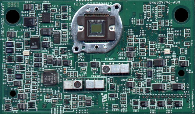
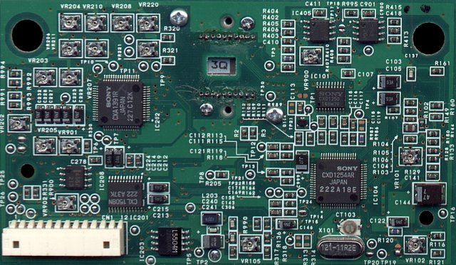 CCB-C35T PCB front view with the lensremoved, and PCB rear view.(Click on the smaller pictureto view it full size. Use your browser's "back button" to return. Thisapplies to virtually all of the images used in this article).
The CCB-C35T is a complete color CCD video camera module. Very compact, it measures in at 4" x 2.5"x 1.25" (HxWxD). Optics consist of a fixed focus / aperture lens that has an "in focus" field from approximately 18" to 9 feet. The module contains a Sony color CCD (Charge Coupled Device) image sensor with a resolution of 510 pixels x 492 lines. All of the necessary clocks, pulse generation and signal processing functions are performed in 6 application specific ICs. It produces Y/U/V component video as well as H. Drv, V. Drv and Composite Sync. All power and signal interfacing is accomplished by way of a small 12 pin connector on the back side of the PCB. In operation, the camera draws less than 1W of power, making it ideal for battery powered operation.
.
Background History:
 CCB-C35T placed as a workstation camera and the desk top phone model:(Photo courtesy of Lucent Technologies). The CCB-35T Color CCD module was manufactured by Sony, for AT&T (now Lucent Technologies), in 1993. It was used in the AT&T VideoPhone 2500 which was discontinued in 1995. There is no longer any tech support for any AT&T VideoPhone products. This HTML document represents hundreds of hours of research (detective work) to reassemble the critical pieces of information that will be required to complete this "home brew" project. So far as I know, this is now the premier source of available information for the CCB-C35T Color CCD Camera Module.
.See what Lucent's Video Conferencing Group is doing right now!.Here's a real good article about video conferencing by Jeff Evans.Here is the Great Grand Pappy of the AT&T VideoPhone 2500!.
Let's get technical:
.
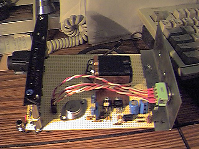 CCB-C35T's Block Diagram and a pictureof my initial breadboard:(CCB module is to the right, being viewed edge on. Not the 9V batteries). The first thing many of you will notice, is that this module contains, 17 pots, 1 variable capacitor and 2 tunable inductors. Do not adjust any of these settings! under any circumstances! This module was preset, at the factory, in a custom test jig, under highly controlled conditions. It is unlikely that you could set up the module any better than the technicians at Sony. Until we reach the fully operational stage of operation, it is more likely that you will inject unnecessary unknowns into the experimental process. For the present, presume that your CCB-C35Tis alligned perfectly.
.
Even after a functional stage is reached, where tweaking may be beneficial, do not tune the two inductors on the front of the board. The following applies to all circuits with tunable inductors: Once an inductor is tuned, barring gross failure of the inductor, it should NEVER need retuning again! The two tunable inductors, on this board, will appear to do nothing when you twist them. However, this is not the case. They effect the group delay charactersitic of those filters and will have an impact on the overall quality of the final, full color image. Once again, DO NOT adjust anything, yet! You have been warned.
.
In part 3, The Video Encoder, I will address the issues involved in "tweaking" the appropriate settings.
.
The CCB-C35T contains a CCD (Charge Coupled Device), master clock oscillator, TV sync generator, CCD timing generator, CCD (video) signal reconstruction, video AGC and Color Mosaic processor. The CCD is the image sensing device,comprised of a rectangular array of photosensitive sites, arranged in 504 columns and 492 rows. Over this array of photo sites, is the Mosaic Filter, which allows the otherwise color blind CCD to sense color. The clock oscillator is divided down many times, by dozens of digital counters, which are further decoded to produce dozens of pulse waveforms to drive the CCD, the signal reconstruction amplifier and color mosaic processor. They are also the source of the conventional television synchronizing signals.
.
The color mosaic processor has the toughest job of all. It must sort the incoming pixels based on which color filter they represented, synthesize the luma signal, restore resolution lost in the process, and then make sure all of the components are properly registered. This process is beyond the scope of this article, but I may address it again in the future. Suffice it to say that the video component signals produced by the CCB-C35T are called: Y/U/V. Y is the luminance or brightness component of a scene, exactly the same as B/W tv. Luma for short. U/V are two signals that represent only the color component of a scene. These qualities are HUE and SATURATION. Hue is the "color", like "red", "purple", "green", etc. Saturation is the "richness" of a given hue. For instance, red or pink will have the same value for hue, but will differ in the amount of white light each one contains.
.
(In the USA, U/V are called R-Y/B-Y, but I've chosen U/V for the reason of "less typing")
.
Approximately half of the active devices on the CCB-C35T, including the CCD, have been discontinued. Sony does not and can not provide direct support for obsolete products. Data sheets for their current CCD imagers and support devices can be found at:Sony Semiconductors - CCD Area Sensors.
Sony does have a listing of discontinued products that you can check to determine if you have an obsolete part. It is at:
.Sony Semiconductor - Discontinued Product List.
The best place for finding data on obsolete CCD's and support devices is at:
.The eio CCD Hyper-email Discussion Group..
Primary Devices / PartialParts List:
.
IC1 ICX044AKA CCD Chip (Sony, Color, 510 x 492.) (I used ICX054AK as a reference)
IC104 CXD1254AR CCD Complex Timing Generator (I used CXD1257AR as a reference)
IC101 CXD1250M CCD Vertical Clock
IC102 CXA1390AR Sample & Hold and AGC functions
IC202 CXA1391R Color Mosaic Signal Processor /
IC203 CXL5504N 1H Luma Delay Line
IC201 CXL1508N * Dual? 1H? Chroma Delay Line?
X101 9.545445Mhz * XTAL Master crystal (Freq. is a guess based on CXD1257ARdata sheet)
.
* No data sheets available.
CN1- Pin Definition:
.
1. +15V Analog power supply - 10mA 7. B-Y/V Video Color Component #2
2. +5V Digital power supply - 140mA 8. HDrive Output: Horizontal Drive
3. -9V Analog power supply - 10mA 9. VDrive Output: Vertical Drive
4. GRND Return path for ALL supplies and signals 10. ?? Unknown - Color Balance?
5. LUMA Output: Monochrome Video Component 11. ?? Unknown - Color Balance?
6. R-Y/U Output: Color Video Component #1 12. CSYNC Output: Composite Sync
.
The Power Supply: My Power supply schematic:.
This is my recommended design. Many other forms are possible. What I wanted to emphasize here was the use of a 100% linear design. Avoid switching power supplies if you can. If you only have a switching supply, then go with it. Just remember that you may have to add additional power line filters after your module is up and running. Then again, you might not...
.
This is very important! Notice the two RC filters that I installed just before the pins 1 and 3 of the camera module. During power up, the negative supply must turn on slower than the positive supply. If this rule is not met, the module becomes permanently damaged. DEAD! I had not installed the multi gang switch in the early testing phase. This resulted in different turn on time delays for the 3 power supply inputs. In fact I used a computer style jumper plug (shunt) for the +18V switch! (the two 9V batteries I used early in the design.)
.
The symptom of this mode of failure are excess current draw by the -9V input. LOTS of excess current. The CDX1250 chip will be roasting hot! You will know..... If this happens to you, IMMEDIATELY STOP! Unplug everything. Turn off your soldering iron and test equipment.Then, curse, kick and shout, like I did. It won't fix the camera, but it lets off steam.
.
I added the multigang switch and the RC filters during the process of analyzing the death of camera #1.
.
Black and White Operation:
.
Now that your power supply is finished and tested, it's time to hook everything up and determine if our camera module is working. For this test, a Simple "Go / No-Go" answer is good enough. The logical choice is to feed the Y video output directly into a video monitor. If you like, give it a try. It works - sort of. The picture on the monitor looks OK - 88% of the time. Now and then it will bend or roll, depending on the presence of extremely bright or dark scene content. A quick check with my trusty oscilloscope confirmed what I suspected. There are no sync pulses on the Y video output! There is a little bit of a glitch, a negative pulsing spike, leftover from an upstream clamp circuit perhaps. It is this spike that my monitor seemed to accept as async pulse most of the time. You may get different results, depending on your video monitor and other factors.
.
I knew that the module had a seperate composite sync output. So, I grabbed a couple of 1K ohm pots out of the old junk box, soldered them into a simple current summing circuit and "twiddled" them until I had a stable picture on the TV monitor! (Don't bother to send me hate mail, telling me how un-scientific that was. I know!) Some free advice: In "the real world", where most people work, success is measured by the end result, not by the methods!
.
The final step was to measure the values that I had twiddled the pots to, and replace them with the appropriate fixed value resistors. They turned out to be 200 ohms and 75ohms.
.
Notes:
1. The video level is wrong (low). So, adjust the monitor's contrast.
2. The Y out signal is AC coupled. So, adjust the monitor's contrast continuously!
.
To test B/W operation you will need the following components:
1 - Video monitor. Color or B/W - As long as it has a 75 ohm direct video input. A VCR connected to a television receiver will also work well for this part of the test.
1 - Video cable with the appropriate plug to fit the input jack of the monitor or VCR.
1 - Resistor, 75 ohm, 1/8 W
1 - Resistor, 200 ohm, 1/8 W
.n - of your best friends to say, "Ooooooh!" and "Aaaaaaaah!" when you demonstrate your video abilities!
.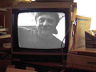
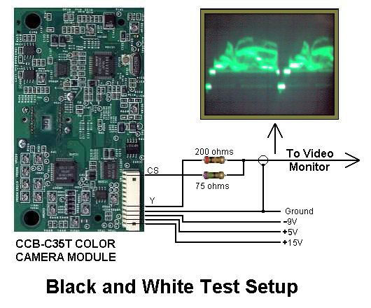 The Author admires his grinning mug! AND The Black and White Test Ciruit! This circuit is crude, but works. It actually works very well! Click on the first picture to observe how happy you will be when you get your camera project to this point! Click the second picture to see how easy it is! What are you reading this for? Get on with it!
. End of Part 1.
In part 2, I'll show you how to construct a "Color Matrix" so we can see the full color fidelity of the CCB-C35T on an RGB video monitor - Like that old VGA computer monitor you've got rusting away in the garage.
.
In part 3. I'll show the construction plans of a complete NTSC encoder, which will take the Y/U/V output of the CCB-C35T and give us back NTSC composite video.
.
About the author:
.
LabGuy was born in Berlin, Germany, in late 1957. As a baby, his nickname was Sputnik! But he feels that nickname has "gone around" too much and prefers "LabGuy" His travels have taken him through 28 of the 50 United states, Germany, Austria, Canada, Hong Kong and Mainland China. LabGuy lives and works in San Jose, California. In the middle of the Silicon Valley.
He has ended up there, because he really loves electronics! Especially any kind of electronic whats-it or thing-a-ma-bob that will detect or recreate images. He repaired his first television at age 11, built an all vacuum tube video camea, from scratch, at age 15. In 1976, he joined the U.S, Air Force, where he chased satellites all day AND all night. (He really likes coffee to this day!) In 1977, LabGuy bought his first video recorder and joined "Metrovision" the club that owned WR4AAG, the very first ATV repeater.
In real life, where people wear too many suits and ties, LabGuy calls himself Richard N. Diehl. But, he prefers LabGuy because.. . well . . . . he's a lab kind of a guy! (What else?) Visit LabGuy's Home Page for more video insanity and general purpose madness.
Everything you ever wanted to know about LabGuy's World, but didn't know where his home page was!
Return to eio's Home Page or view Articles/Reviews, Order Information, Events, Hot Deals, Forums, Discussion Groups, Weekly Specials, Monthly Specials, Specials, Inventory, Resources, 99 Cent Page or E-Mail us