 US
US
The system we are designing will test an individual's blood alcohol level by analyzing the breath exhaled into our system, in which the sytem will decide whether to let the individual start the car. We will be using an "Ensure" made by "Alcohol Countermeasures" to measure the blood alcohol level. We will also be including a numeric touch pad (state machine) that will replace the existing key ignition system. The driver of the car will have to key in their pin number instead of using a key. The the driver will then be signaled to breathe into our modified breath analyzer. If the driver passes the test he/she may start the car by pressing a start button that will control the starter for the vehicle.
 Ensure
The objective of this design is to help keep drunk drivers off the road. The system will be designed so that it will be able to interface with all current ignition systems. Our system will also eliminate the use of keys to start the vehicle, therefore eliminating the need for keys. The user of the system will be given audio feedback at each stage (ie. whether they passed the keypad test and then the blood alcohol test). This will be done by integrating standard voice chips into the system. These could be replaced by LED's to control the cost for future designs.
The breath alcohol tester is an electronic device used to test the blood alcohol content (BAC) in a person's blood stream. Several other methods of alcohol detection exist, such as chemical reactions, optical- interference, infrared absorption, and heat generation from a catalytic reaction on a hot platinum wire. These methods, however, have the disadvantages of being difficult to handle and maintain. They are also very expensive and have a very limited lifetime.
This device utilizes a semiconductor sensor to analyze a person's exhaled breath. This method is both simple and affordable. The semiconductor device offers the an added advantage in that it is robust; it is highly immune to shock and vibration, and therefore more reliable.
The sensor consists of a semiconductor material mounted on a ceramic tube; it is protected by a double layer of 100-mesh-per-inch stainless steel screening. When the alcohol tester is turned on, the sensor is heated to normal operating temperature. During this process, oxygen is absorbed into the semiconductor surface. This causes a depletion region to form between the surface and the body of the sensor. In turn, this increases the resistance of the sensor.
When an intoxicated person blows on the sensor, the alcohol is absorbed into the semiconductor surface and reacts with the oxygen that is already there. This decreases the sensor's overall resistance in proportion to the alcohol concentration.
Click here for the circuit schematic
When the alcohol tester is turned on, the heater coil in the sensor is energized with 5 volts from a 7805 voltage regulator (IC5). The circuit cycles through a self-testing and warm-up period. The circuit resets itself to 0-alcohol reading and sets off the ready light.
When an intoxicated person blows into the device and the sensor detects alcohol, its resistance decreases; this changes the input voltage to the detector circuit. The detector circuit is made up of a quad op-amp. The detector circuit is calibrated by 2 resistors (R3 and R4), and the inputs to each section are controlled by a voltage-dividers (R21-R23). As each section is activated, the outputs go low and the sample-and-hold circuitry will latch onto the highest input value and trigger the appropriate LED. Different colored LED’s represent different alcohol levels.
If the detected alcohol level is above the legal limit (0.1%), another op-amp will trigger a buzzer and the LED corresponding to an "over the limit" level of alcohol. This indicates that the person is too drunk to drive.
Click here for a time chart for the CKT
The alcohol tester must be calibrated using the potentiometer; this must be done before initial use and should be repeated after 10 uses.
After a test, the sensor takes a few seconds to ready itself for another test. During this time, the circuit resets itself and the ready light will come on again.
This design includes a low battery light indicator. When this light comes on, the batteries must be changed to insure accurate test results.
To get accurate test results, do not drink or smoke 15 minutes prior to taking the test.
 Block Diagram
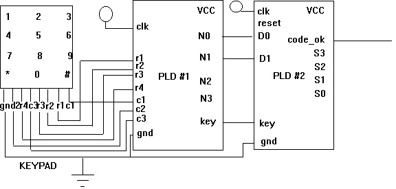
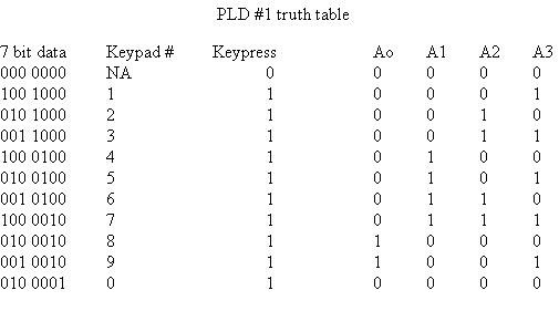
To implement the combination number phase of our ignition system, we used a standard ten number key pad out of a push button phone with two PLDs (programmable logic device). The first PLD was used to convert the 7 bit number produced by the key pad (first 3 bits represent the 3 columns and the second 4 bits represent the 4 rows) into a 4 bit number (N0-N3 on PLD #1) which represents the numbers 1-9 in binary. The first PLD also outputs a 1 bit number called the keypress bit, which will be high if any of the buttons are pressed. The logic handled by the first PLD is shown in the following truth table. The 7 bit numbers which are not shown below do not represent a number on the keypad and will be handled by the PLD as "don't cares". Since these numbers can't be triggered by the keypad they will be ignored.
 PLD truth table
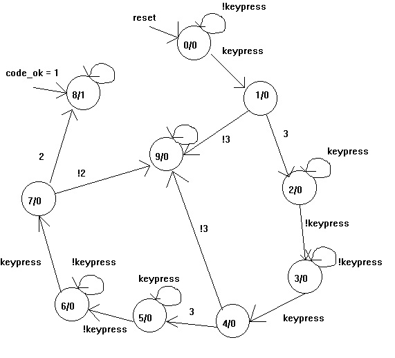
The second PLD will handle the state machine needed to check and see if the three number combination from the keypad actually matches our security code - 332. Since state machine logic gets rather complicated we had to limit our security code numbers to two binary bits (numbers 0-3 on the keypad) so that the logic would fit onto one 20 pin PLD. We are using the state machine shown below to handle this task. For the state machine to move from state 0 to state 1 it needs a high input from the keypress. For the state machine to move from state 1 to state 2 it needs the two bit input to equal the first number in our security code - 3. If it recieves a two bit input not equal to 3 it will go to state 15 where it will stay until the reset button is pushed triggering a high at the reset pin. The state machine will then wait for the keypress to go low indicating that the user has let off of the 3 button on the keypad. When this happens the state machine will go to state 3. This process is repeated until the user enters the last number in the security code (2). When this happens the code_ok pin goes high, turning on the blood alcohol tester segment of the ignition system. The state machine stays put in this state until the reset button is pressed. Note that only the two least significant bits are inputed into the second PLD. Thus the numbers 776 would work just as our code of 332 does. This decision was made for simplicity, and a more advanced and usefull combination device would need 4 bits to the input of the second PLD and more than 3 numbers in the combination.
 Flow Graph
With the completion of our system we relized that this idea could be very effective against drunk drivers. We found a couple of commercial models which range from $500-$700 dollars. The final cost of our sytem was $200. Note that our system included a keyless ignition control system and a voice chip to signal the driver that they could start the car.
The most difficult part of our design was bring together all the different systems and intergrating them into a robust and reliable product. When testing the design we noticed that it would be aggravating for the driver to wait 35 seconds for the alcohol sensor to warm up. In future designs of this system the designers should look at ways of speeding up this process.
The sensor, which claims to be a blood alcohol tester, actually measures the amount of alcohol that is in your breath. We noticed that if you drank on sip of beer and quickly breathed on the sensor that you would be regestared as legally drunk when in fact you weren't. Overall, the system work better than we expected and hopefully the state will look at using such system to keep drunk drivers off the road.