THE ELECTRIC WAVE ![]()
NOISE GENERATOR
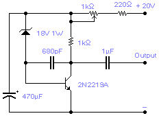 Sometimes
there is a need for a noise generator: this will work well in the audio range and, without
the 680pF capacitor, will extend in the radio frequency range up to 20-30MHz. Voltage
output may vary from 1Vpp to several volts depending on the type of zener used, older
types have generally a higher noise; the zener voltage will influence the output level as
well: the higher the voltage the higher the output level. Adjust the 1k pot for the
required level.
Sometimes
there is a need for a noise generator: this will work well in the audio range and, without
the 680pF capacitor, will extend in the radio frequency range up to 20-30MHz. Voltage
output may vary from 1Vpp to several volts depending on the type of zener used, older
types have generally a higher noise; the zener voltage will influence the output level as
well: the higher the voltage the higher the output level. Adjust the 1k pot for the
required level.
ELECTRONIC I CHING
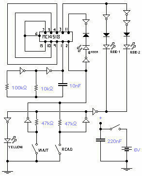 This
circuit is the electronic emulation of the I Ching, a form of divination originating in
China. In the classical form, the response is obtained by the manipulation of 50 sticks
or, more practically, by tossing 3 coins. The process must be repeated 6 times in order to
complete what is called an hexagram. The various combinations given by the 6 readings are
then read with the help of a book: the I Ching in fact or book of changes, used as a guide
for the interpretation of the results. As the hexagrams look very much like a binary code,
with additions and subtractions to go from one hexagram to the other, I thought that a
hardware implementation could be feasible. The circuit reflects faithfully the chances of
the I Ching: it is based on a counter which repeats a certain sequence, like a wheel. You
may stop this rotation and read the counter status. In order to operate it you have to
power it on and push "wait", the yellow LED will be on and all other LEDs will
be off. After a short while push "read", the yellow LED will go off and the
other LEDs will be enabled and the information stored in the double counter will be
displayed: either red 1 or red 2 will go on representing a YIN and YANG line respectively.
The same line becomes a moving line if also the green LED is lit. This is the first line
of the hexagram: repeat the process 6 times by pushing again "wait" and so on.
The whole circuit uses 3 ICs: one double counter and two hex inverters MC14049B. Supply
voltage can be anything between 3 and 9V.
This
circuit is the electronic emulation of the I Ching, a form of divination originating in
China. In the classical form, the response is obtained by the manipulation of 50 sticks
or, more practically, by tossing 3 coins. The process must be repeated 6 times in order to
complete what is called an hexagram. The various combinations given by the 6 readings are
then read with the help of a book: the I Ching in fact or book of changes, used as a guide
for the interpretation of the results. As the hexagrams look very much like a binary code,
with additions and subtractions to go from one hexagram to the other, I thought that a
hardware implementation could be feasible. The circuit reflects faithfully the chances of
the I Ching: it is based on a counter which repeats a certain sequence, like a wheel. You
may stop this rotation and read the counter status. In order to operate it you have to
power it on and push "wait", the yellow LED will be on and all other LEDs will
be off. After a short while push "read", the yellow LED will go off and the
other LEDs will be enabled and the information stored in the double counter will be
displayed: either red 1 or red 2 will go on representing a YIN and YANG line respectively.
The same line becomes a moving line if also the green LED is lit. This is the first line
of the hexagram: repeat the process 6 times by pushing again "wait" and so on.
The whole circuit uses 3 ICs: one double counter and two hex inverters MC14049B. Supply
voltage can be anything between 3 and 9V.
WINDSCREEN LOOP AERIAL
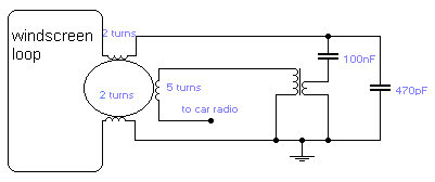 If
you do not like the whip antenna on your car, you may try this alternative circuit. A
one-turn loop is installed in the windscreen of the car, keeping possibly away from the
metal structure of the car. This loop is terminated in a 6.5mm ring core suitable for VHF
use. MW and LW are gathered for by the other coil taken from an old MW radio. This is the
oscillator coil of the receiver with all capacitors removed and with the slug fully in.
Performance depends very much on the components used. In most cases there was no
difference compared with a whip antenna although an improvement was found when traveling
in tunnels.
If
you do not like the whip antenna on your car, you may try this alternative circuit. A
one-turn loop is installed in the windscreen of the car, keeping possibly away from the
metal structure of the car. This loop is terminated in a 6.5mm ring core suitable for VHF
use. MW and LW are gathered for by the other coil taken from an old MW radio. This is the
oscillator coil of the receiver with all capacitors removed and with the slug fully in.
Performance depends very much on the components used. In most cases there was no
difference compared with a whip antenna although an improvement was found when traveling
in tunnels.
ZERO CROSSING AC SWITCH OSCILLATOR
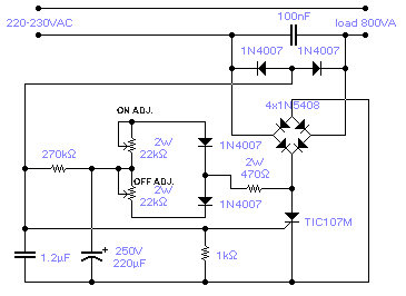 The circuit shown will switch on and off a resistive or inductive load up to 800VA
with the possibility to adjust both the on and off period. Switching takes place during
the zero crossing of the sine wave. The switch on point is around the zero crossing but
pinpoint accuracy is not guaranteed due to the analogue nature of the circuit. The on
period is adjustable between 0.3 to 4sec while the off period is adjustable between 0.2
and 10sec. The chosen SCR has a sensitive gate: this avoids the use of a large
electrolytic capacitor. Frequency of operation is fairly stable although it is slightly
affected by temperature, supply voltage and loading conditions.
The circuit shown will switch on and off a resistive or inductive load up to 800VA
with the possibility to adjust both the on and off period. Switching takes place during
the zero crossing of the sine wave. The switch on point is around the zero crossing but
pinpoint accuracy is not guaranteed due to the analogue nature of the circuit. The on
period is adjustable between 0.3 to 4sec while the off period is adjustable between 0.2
and 10sec. The chosen SCR has a sensitive gate: this avoids the use of a large
electrolytic capacitor. Frequency of operation is fairly stable although it is slightly
affected by temperature, supply voltage and loading conditions.
HIGH VOLTAGE GENERATOR
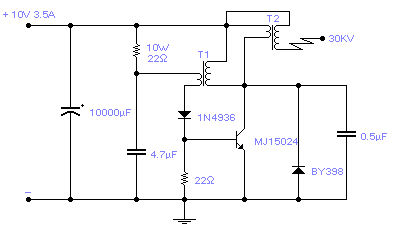 Easy
to build, this high voltage generator is capable of generating up to 50KV but the
breakdown voltage of the coil limits the voltage to a value somewhat lower. T2 is the
ignition coil of a car and also the 0.5µF capacitor comes from the same place: actually I
suggest using only this type of capacitor. T1 is a small transformer with a laminated iron
rod, with a square section of 7x7mm, 57mm long with 75 turns on the collector side and 25
turns on the base side made with a 1mm enamelled wire. Its implementation is not critical
and I expect that the circuit will work with a wide variety of transformers including
ferrite ones. Try to invert one of the windings if the circuit does not oscillate. The
transistor will stay quite cool and does not require a radiator if it is assembled on a
metal case; otherwise a small 5ºC/W radiator will suffice. Frequency of operation is
around 1.2KHz.
Easy
to build, this high voltage generator is capable of generating up to 50KV but the
breakdown voltage of the coil limits the voltage to a value somewhat lower. T2 is the
ignition coil of a car and also the 0.5µF capacitor comes from the same place: actually I
suggest using only this type of capacitor. T1 is a small transformer with a laminated iron
rod, with a square section of 7x7mm, 57mm long with 75 turns on the collector side and 25
turns on the base side made with a 1mm enamelled wire. Its implementation is not critical
and I expect that the circuit will work with a wide variety of transformers including
ferrite ones. Try to invert one of the windings if the circuit does not oscillate. The
transistor will stay quite cool and does not require a radiator if it is assembled on a
metal case; otherwise a small 5ºC/W radiator will suffice. Frequency of operation is
around 1.2KHz.
SENSITIVE GEOMAGNETIC DETECTOR
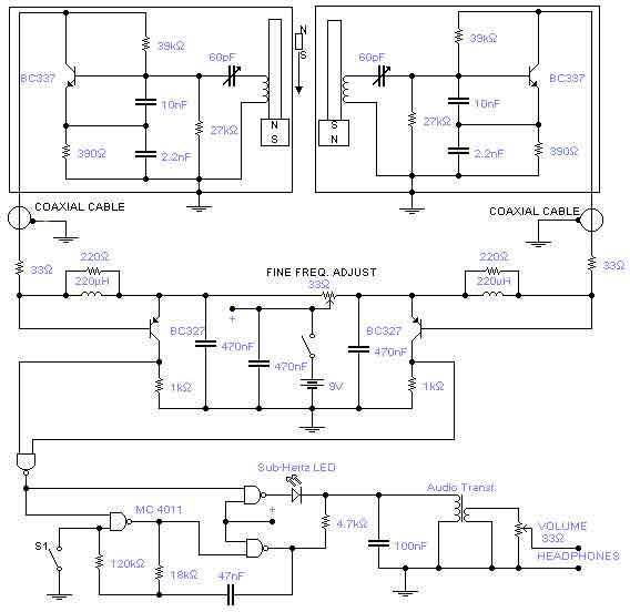 This is a rather sensitive circuit which will detect minute
variations of a magnetic field, particularly the Earth magnetic field. The principle is
based on an audio beat tone generated by two identical oscillators. These must be built in
the same manner with the same type of components. In this way we minimize influence from
temperature and voltage variations. The two oscillators, called probes, are housed in
plastic boxes padded, on the inside, with copper wires terminated in one point only and
running parallel to the ferrite rod. This rod, together with the coil was removed from an
old Medium Wave radio and a small and powerful magnet was glued on one side. An extra
magnet was placed on the outside of one of the boxes in order to set the initial or
"zero" beat tone. This magnet is rotated or moved up and down until you hear the
right frequency. A small hole is made in each plastic box in order to adjust the trimmer
capacitor. Switch S1 will enable the sub-Hertz detector: in this way you will be able to
hear the beat note even if the difference between the two probes is below the threshold
level of around 20Hz and you will pick up differences well below 1Hz. The two probes are
connected to the main box using standard RG58 coaxial cable tested up to a length of 15m.
Operating frequency is 1.25MHz and it is sensitive enough to feel the
rotation of a speaker magnet 2m away.
This is a rather sensitive circuit which will detect minute
variations of a magnetic field, particularly the Earth magnetic field. The principle is
based on an audio beat tone generated by two identical oscillators. These must be built in
the same manner with the same type of components. In this way we minimize influence from
temperature and voltage variations. The two oscillators, called probes, are housed in
plastic boxes padded, on the inside, with copper wires terminated in one point only and
running parallel to the ferrite rod. This rod, together with the coil was removed from an
old Medium Wave radio and a small and powerful magnet was glued on one side. An extra
magnet was placed on the outside of one of the boxes in order to set the initial or
"zero" beat tone. This magnet is rotated or moved up and down until you hear the
right frequency. A small hole is made in each plastic box in order to adjust the trimmer
capacitor. Switch S1 will enable the sub-Hertz detector: in this way you will be able to
hear the beat note even if the difference between the two probes is below the threshold
level of around 20Hz and you will pick up differences well below 1Hz. The two probes are
connected to the main box using standard RG58 coaxial cable tested up to a length of 15m.
Operating frequency is 1.25MHz and it is sensitive enough to feel the
rotation of a speaker magnet 2m away.
BASIC INFRARED TX-RX
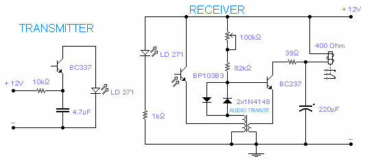 The
transmitting section of this infrared tx-rx is unusually simple but it works rather well:
the infrared LED pulses at a frequency of 160Hz and its range, with its receiver, is
between 2 and 4m depending on the transformer used and the setting of the 100k pot. With
other receivers it may reach a range of 15m, without any lens but with a perfect alignment
between tx and rx. The receiving section uses an infrared phototransistor and an
additional infrared emitter is placed next to it in order to provide a light bias thus
improving sensitivity. The 100k pot. will also adjust sensitivity by setting the right
operating point for the transistor. The supply should be well regulated in order to avoid
self-oscillations. The audio transformer is a small output transformer recovered from an
old transistor radio.
The
transmitting section of this infrared tx-rx is unusually simple but it works rather well:
the infrared LED pulses at a frequency of 160Hz and its range, with its receiver, is
between 2 and 4m depending on the transformer used and the setting of the 100k pot. With
other receivers it may reach a range of 15m, without any lens but with a perfect alignment
between tx and rx. The receiving section uses an infrared phototransistor and an
additional infrared emitter is placed next to it in order to provide a light bias thus
improving sensitivity. The 100k pot. will also adjust sensitivity by setting the right
operating point for the transistor. The supply should be well regulated in order to avoid
self-oscillations. The audio transformer is a small output transformer recovered from an
old transistor radio.
![]() Eager
for more
Eager
for more
 Full astern to main page
![]()
