About Line Noise:
One of the banes of the VLF/LF/MF listener is powerline noise. Down at these frequencies (several MHz and below) the energies of various electronic switching devices (such as light dimmers, motor controllers, fluorescent lights, etc.) are very strong. There are several reasons for this: Harmonics tend to decrease in energy with increasing frequency, and at these low frequencies, their energy hasn't dropped off by much. Another reason is that the filters built into devices such as light dimmers just aren't effective below several hundred kilohertz. Finally, these devices are typically connected directly to the house wiring and are therefore conducted into equipment and radiated on inside wiring and powerlines.
Efforts to rid yourself of this type of noise may be hard-fought battles, particularly at LF and below: A filter that works effectively at LF frequencies is likely to be too large to fit within the fixture or enclosure of the device for which it is intended.
There are several other ways to minimize the impact of powerline-related noise on your listening:
Assuming that you have tried all of these but you need more
help, then a noise blanker may be for you.
Most of today's radios contain something referred to as a "noise blanker."
Those who have used these noise blankers also know that most of them have
only limited effect on powerline-type noise. Many of them will also
cause large amounts of intermodulation distortion in their operation, obscuring
weaker signals. A few noise blankers (such as the one in the Drake
TR-7/R-7 or R-4 lines) do work well, but these blankers (as well as others)
are affected by nearby strong signals. Furthermore, they don't usually
work on but the first "layer" of line noise (more on this later.)
A Brief Analysis of Line
Noise:
|
Line noise typically occurs on both sides of the power line sinusoid. That is, it produces pulses at twice the line frequency (we'll assume throughout this page that we are talking about a U.S. power system) at 120 Hz. Even so, this noise often has strong 60 Hz components as well. The result of this is that powerline-related noise produces energy every 60 Hz across the spectrum. To further complicate matters, AC power is distributed by the utility in three phases, each being 120 degrees from the other phase: This can seem to "multiply" the number of noise pulses that occur during each cycle of the powerline's waveform.
The noise is produced by the abrupt switching of some device (i.e. a triac in a light dimmer.) This fast switching produces noise pulses extremely rich in harmonics. The timing of this pulse with respect to the "beginning" of the sinusoid (let's say that this is where it crosses zero on the positive-going portion) can vary, depending upon when the offending device triggers. This can also be offset in timing if, say, the device is operated on a different phase of a three-phase power system, for example. This fast switching produces a pulse that is very narrow (a few tens of microseconds or less by the time it reaches your antenna.)
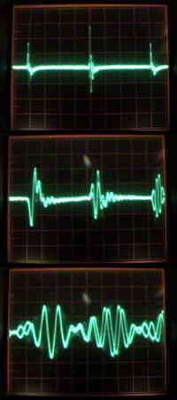
What about filters? While it is true that with a narrower filter less noise energy will be intercepted, there is another problem: Narrower filters tend to stretch noise pulses. The three images to the right demonstrate this. These images are from a line-triggered oscilloscope connected to the audio output of a Drake TR-7. Three filter settings are used (top to bottom) with the first one being a 12 KHz filter (only the first IF filters are used) followed by a 2.2 KHz SSB filter and a 300 Hz CW filter.
With the 12 KHz filter (the top image) the vast majority of the noise pulse energy occurs within 1/8 of a division (about 250 microseconds) with a bit of ringing extending through 1 millisecond. Contrast this with the middle image depicting the same pulse, but through a 2.4 KHz SSB filter. Notice that the pulses now drag out to longer than 1 millisecond, about 4 or 5 times longer than before. The bottom image shows the same pulse through a 300 Hz CW filter: The pulses are actually beginning to run together.
It is true that most receiver noise blankers are placed earlier in the IF of a receiver - before the main bandwidth-determining filters, but even these receivers do have (wider) bandpass filter that tend to stretch out the pulses somewhat.
All is not lost: With powerline noise, we have an advantage over random noise in that we know very precisely its repetition rate - 60 or 120 Hz (in the U.S. and a few other countries, at least.) Furthermore, this noise source is most likely powered from the same power grid as your equipment (even if it isn't on the same phase as you) and thus you have a ready-made reference for the noise-pulse frequency. What is not known is the precise position and width of the offending pulse.
(By the way, the noise blanker described reduced the above "light dimmer noise" by well over 35 db.)
Deleting the offending noise
pulse(s)...
 |
As can be observed above, simply muting the pulses at audio is not a very good solution due to the stretching of the pulses by the receiver's filters. If this fact weren't the major concern, there is the problem of the receiver's AGC action attenuating the desired signal: The noise will set the AGC to levels based on the strongest signal being receive (even noise) - but if the desired signal is, say, 15 db below the noise peaks, the AGC will bury that signal 15 db in the audio... among the stretched noise pulses...
What we need to do is blank the RF during the noise pulse before it gets to any of the receiver's filters: Since the noise pulse itself is (usually) of very short duration, we don't need to blank it for very long. The most obvious place to do this is at the antenna connection. This may be done several ways. The blanking gate described here uses PIN diodes in an attenuator arrangement. This attenuator provides attenuation that is related to the current applied to its diodes and is fairly "linear" even when only partial attenuation is occurring. This is important if you want to minimize the amount of intermodulation that the noise blanker will cause. The use of MPN3404 PIN diodes is intentional here. This circuit will work with ordinary 1N914/1N4148-type diodes, but expect performance to be worse.
Most important to intermodulation reduction is careful control of the slew rate of the blanking pulse. If one were to simply employ a switch that turned the antenna on and off, the switch itself would cause significant harmonics and the blanker itself would cause what sounds like line noise. If one (relatively) slowly turns the attenuation on and off during the blanking, you can greatly reduce the possibility of intermodulation and reduce the bandwidth and intensity of the "blanking sidebands" that are necessarily created during blanking (we are amplitude modulating our received signals with the blanking pulse, remember...)
As it turns out, while there is typically one major noise pulse causing most of the buzzing, but there may be several other noise pulses occurring during different times. That is, if you blank just one set of the offending pulses, there may be another set that you are now able to hear that also obscures the desired signal. You may wish to have the ability to set up individual blanking pulses for the various "layers" of noise.
Design philosophy:
There are several schools of thought when designing noise blankers. "Normal" noise blankers have fast-acting blanking gates - a necessity because these blankers are typically "asynchronous," operating by first detecting the rising edge of the pulse, and then blanking it before much of its energy finds its way into the receiver. Clearly, if you are going to blank a pulse that you have just detected, you need to act quickly.
With a synchronous noise blanker such as the one described here, you have the luxury of knowing precisely when a pulse is going to appear. You could use a fast-acting blanking gate or you could use a slower one. What's the difference, then? Which one is better?
The answer isn't necessarily a simple one and each has its own set of tradeoffs. About fast-acting blanking gates:
The use of a doubly-balanced diode-ring mixer (used as a variable attenuator) can be used to mitigate this problem. The problem with using a diode ring mixer instead of the PIN diodes is that their cost is much higher, and they have a very definite low-end frequency response which may make them unsuitable if very low LF or VLF reception is desired.
Description of the circuit:
What we need is a device that will produce a blanking pulse that has two adjustable parameters: Position and width. The position is relative (in this case) to the zero crossings of the 60 Hz line frequency (which occur at a rate of 120 Hz) and the width is, well, width...
The schematic of the unit described may be found here. (Schematic updated/corrected on 23 April, 2002)
Schematic versions:
 |
The blanker is powered by a 18 volt AC power cube. This power is filtered and isolated (at RF frequencies) with a bifilar-wound inductor removed from a defunct computer switching power supply. This inductor has several millihenries of self-inductance and it prevents noise that might be conducted from the power cube (from the power line) into the receiver itself.
This power is then half-wave rectified and filtered and applied first to a 7818 regulator for a stable 18 volt DC supply (for the blanking drivers and for powering the receive antenna on the coaxial cable) and then filtered and regulated to 5 volts for the timing logic. The capacitor and series resistor across the diode are used to suppress any "hash" that might be produced by the diode rectifier.
A portion of the "pre-rectified AC" is extracted, filtered, AC coupled (to remove any DC bias) and applied to U2C which is wired as a comparator to produce a 60 Hz 18 volt square wave. This square wave is resistively divided down to approximately 5 volts and applied to U3B, a 74HC86 which buffers the 60 Hz square wave and applies it to U3A which is wired as an edge-detector. The resistor/capacitor combination on its input cause this section to produce a narrow pulse on each transition of the 60 Hz square wave, thus producing a 120 Hz pulse train. This train is buffered by U3D and is made available for the blanking-pulse generators. The remaining section (U3C) is simply tied to U3D so that it's input isn't floating and is therefore unused. (Yes, I should have tied it to to either the ground or the 5 volt supply, but I was lazy...)
The 120 Hz pulse train is applied to U1B, a 74HC123, a dual one-shot timer. U1B is the "position" timer and has a period that is adjustable from a few microseconds to the entire duration of the 120 Hz pulse repetition interval to allow blanking to occur at any point in the period of the pulse train. The output of this is first section is sent to U1A.
Since U1A is edge-triggered, it responds only to the rising edge of the pulse from U1B - the end of the timing period. The section of U1A operates exactly like the U1B section, except that its timing range is restricted to approximately one-third of the interval of the 120 Hz pulse train. This section functions as the "width" generator for the blanking pulse.
The finished blanking pulse appears on pin 4 of U1A and it is at this point that this blanker generator may be "diode-ORed" with the outputs of other pulse generators. If it is desired that more than one blanking pulse is needed (at least two are recommended) then the next section would be connected at this point. For enabling/disabling a blanking generator, a switch (which may be mounted on the rear of the "width" control) is placed on pin 3 of U1A to enable/disable the timer. For a single section blanker (or for the first of several blanking channels) this may be simply tied to +5V.
U2D, an Op-Amp section, is used as a comparator and it takes the diode-ORed
input from the pulse generator(s) (using a 10k pullup resistor) and generates
inverted 18 volt blanking pulses. This pulse is then shaped by U2A
which is wired as a 3rd order lowpass filter. A 100k resistor limits
the maximum output to prevent clipping of the amplifier at the 18 volt
rail and thus prevents distortion (and the ensuing harmonics) from the
blanking pulse. A switchable 0.018 microfarad capacitor allows selection
of a lower slew rate to allow the blanker to be used at lower LF frequencies
(more on this later.)
 |
The filtered output of the blanking generator is applied to the PIN diodes through a resistor (for current limiting) and across a capacitor and through an inductor (for RF decoupling.) When the voltage is high, current flows through the two PIN diodes, turning them on. When the voltage is off, the diodes do not conduct and high isolation is obtained.
Surrounding the PIN diode network are other inductors and capacitors that allow for power passing and insertion to allow active antennas to be powered by the blanker's power supply and/or the receiver.
Construction notes:
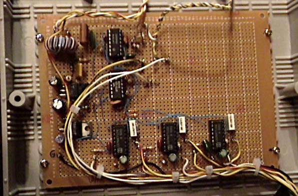
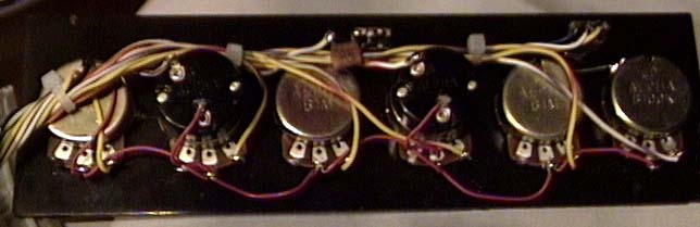
The prototype unit (shown in the pictures) is a three-channel synchronous
noise blanker. (The schematic of the noise blanker is here.)
Although two channels usually suffice, there are (rare) instances where
all three are required.,
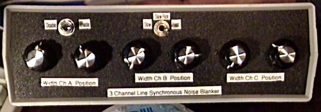 |
The front panel shows six potentiometers: One for position,
and another for width for each of the three channels. Channels
2 and 3 (the middle and the one on the right, respectively) have switches
mounted the rear of their width control pots and these switches
are used to disable their respective channels. They are placed on
the width control so that the channel may be disabled without disturbing
the pulse position settings. Each of these pots is wired such that
counterclockwise rotation corresponds to the shorter timing interval for
the associated timer (i.e. "earlier" blanking pulse for the position
control, or "narrower" blanking pulse for the width control.)
 |
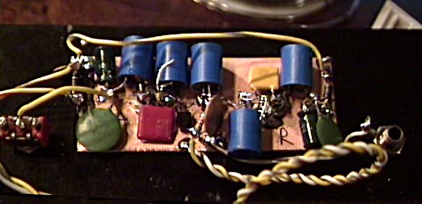
The PIN diode attenuator is constructed on a piece of circuit board
material and is mounted using the antenna connectors (RCA connectors, in
this case.) This provides a good "RF" ground, mechanical rigidity,
and minimizes extraneous RF pickup or radiation. 1.5 and 2.2 microfarad
ceramic capacitors (precise values are not critical) are used for DC decoupling
and these values are sufficiently large enough to allow for minimal attenuation
at VLF frequencies. If such large-value ceramic capacitors are not
available, electrolytic capacitors may be used (observe polarity!)
If response at such low frequencies (below 10 KHz) is not needed, lower-value
capacitors may be used. It is recommended that electrolytic capacitors
(if used) are paralleled with some 0.1 uf ceramic capacitors to minimize
losses that electrolytics often exhibit at higher frequencies.
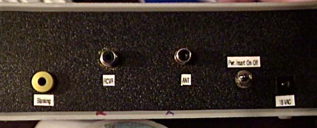 |
With my receiver (a Drake TR-7) I have an "LF Interface box" that puts power on the LF antenna input connector to power an active antenna. Diodes are employed to steer power from the receiver to the antenna and from the noise blanker. A switch is used to enable/disable this power - useful if using a passive antenna.
It is recommended that the bodies of the potentiometers and switches be grounded to reduce "hand effects" and to protect the CMOS circuitry from static discharges. It is also strongly recommended that the timing capacitors on U1A and U1B (the 0.068 and 0.022 uf units) be (relatively) temperature-stable devices such as mylar or polyester: Ceramic devices in this capacitance range are not stable with temperature and you will be plagued with temperature-related drift of the position and width adjustments.
Operation of the unit:
Most of the time, operation of just one blanking channel will eliminate most of the noise. Even if two blanking channels are ultimately required, you start out with just one. The noise blanker is set up thusly:
Operational notes and comments:
There are a few comments about a synchronous noise blanker, what the blanker will and will not do:
Other pages at this site:
The CT MedFER Beacon page - This page describes a PSK31 MedFER beacon.
The CT LowFER Beacon Archive - Some pictures/info about the "CT" LowFER beacon of the late 1980's. (Includes QSLs and sounds from some other beacons of the time.)
"QRSS and you..." - Using absurdly low-speed CW for "communications"
Using your computer to ambush unsuspecting NDBs - A brief description of how Spectran may be used when trying to receive NDBs.
For more information on PSK31, MedFER, and LowFER experimentation, check these other fine sites:
The PSK31 "Official Homepage" - Has articles, software, links to other pages
"Novel Robust, Narrow-band PSK Modes for HF Digital Communications - This is an excellent article about using PSK modes on HF
The Longwave Club of America: "The World of Radio Below 500 KHz" - Also covers MedFER operation
The AMRAD LF Project- AMRAD (Amateur Radio Research and Development Corporation) is doing some LF experimentation.
The KA2QPG Longwave Page - Databases, files, and archives pertaining to Long/Mediumwave
K0LR's Page: Dedicated to LF experimenting and homebrewing (includes BPSK info, many other links, etc.)
The K3PGP Experimenter's Corner - Contains articles and links touching on everything "From VLF to Light"
Any comments or questions? Email to: ka7oei@arrl.net
This page copyright 1999-2002 by Clint Turner, KA7OEI and last updated on 20020708